background image

Содержание EZ3 917.258530

Страница 1: ...Assembly Operation Customer Responsibilities Service and Adjustments oRepair Parts CAUTION Read and follow all safety rules and instructions before operating this equipment FOR CONSUMER ASSISTANCE HOT LINE CALL THiS TOLL FREE NUMBER 1 800 659 5917 ...

Страница 2: ...s The mower could suddenly turn over if a wheel is over the edge of a cliff or ditch or if an edge caves in Do not mow on wet grass Reduced traction could cause sliding Do not tryto stabilize themachine by puttingyour foo on the ground Do not use grass catcher on steep slopesv 2 Ill CHILDREN Tragic accidents can occur ifthe operator is not alert to the presence of children Children are often attra...

Страница 3: ...ng order by the operator In the state of California the above is required by law Section 4442 of the Caiifornia Public Resources Code Other states may have similar laws Federal laws apply on federal lands A spark arrester for the muffler is available through your nearest Sears Authorized Service Center Department See REPAIR PARTS section of this manual _ LIMITED TwO YEAR WARRAN ON CRAFTSMAN RIDING...

Страница 4: ...en 19 Cooling Fins Engine 19 Oil Change 18 Oil Level 13 18 Oil Type 18 Preparation 13 Repair Parts 50 55 Starting 15 Storage 27 F Filters Air 19 Fuel 20 Fuel Type 14 Storage 27 Fuse 25 G Gauge Wheels 8 H Hood Removal Installation 25 L Leveling Mower Deck 22 LubricationChart 16 M Maintenance Schedule 16 Mower Adjustment Front to Back 22 Adjustment Side to Side 22 Blade Sharpening 17 Blade Replaceme...

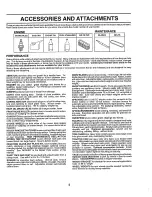
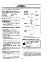
Страница 5: ...lch d scharge or bag clippings bagger optional without changing blades For models not equipped as 3 in 1 Convertible mowers See MOWER in the Repair Parts section of this manual RAMP TOPS AND FEET let you load and unloadtractor from a pickup truck Use with 2 x 8 or2 x 10 lumber ROLLER for smoother lawn surface 36_inch wide 18 inch dameter water tight drum holds up to 390 tbs of weight Rounded edges...

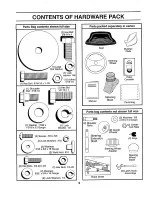
Страница 6: ...e _ I 2 Weld Nuts i0 I_ i nll I 2 Hex Bolts 1 4_20 x 3 4 2 Hex Nuts 1 4 20 2 Washers 9 32 x 5 8 x 16 Gauge 2 Lock Washers 1 4 iltul i Parts packed separately in carton I II i1 1111111111 111111 Seat Mulcher Plate Manual iii iiii ii lul Steering Wheel Steering Boot Video Cassette Parts Bag IIIIIIIH I I ll 11 1111 11 1 I Part s bag contents not shown ful size _ 2 Washers 3 8 _ x 7 8 x 14 Gauge 2 Sho...

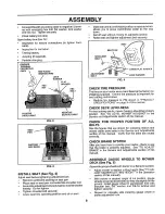
Страница 7: ...rs are horizontal felt to right and slide onto adapter Assemble large fiat washer 3 8 lock washer 3 8 hex bolt and tighten securely Snap steering wheel insert into center of steering wheel Remove protective plastic from tractor hood and grill IMPORTANT CHECK FOR AND REMOVE ANY STAPLES lNSKID THAT MAY PUNCTURE TIRES WHERE TRACTOR 1STO ROLL OFF SKID TO ROLLTRACTOR OFF SKID See Operation section for ...

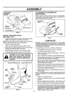
Страница 8: ...E PRESSURE The tires on your tractor were overinflated at the factory for shipping purposes Correct tire pressure is important for best cutting performance Reduce tire pressure to PSI shown in PRODUCT SPECIFICATIONS on page 3 of this manual CHECK DECK LEVELNESS For best cutting results mower housingshould be properiy leveled See TO LEVEL MOWER HOUSING in the Service and Adjustments section of this...

Страница 9: ...CEAND SAT SFACTION FROM THIS QUALITY PRODUCT PLEASE REVIEW THE FOLLOWING CHECKLIST J All assembly instructions have been completed No remaining loose parts in carton z Batten is properly prepared and charged_ Minimum t hour at 6 amps Seat is adjusted comfortably and tightened securely I All tires are properly inflated For shipping purposes the tires were overinflated at the factory Be sure mower d...

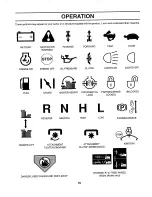
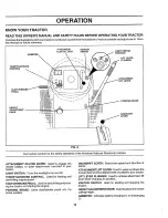
Страница 10: ... OR WARNING 6 ENGINE ON ENGINE OFF REVERSE OIL PRESSURE t FORWARD FAST SLOW CLUTCH LIGHTS ON LIGHTS OFF FUEL CHOKE MOWER HEIGHT DIFFERENTIAL PARKING BRAKE UNLOCKED LOCK LOCKED MOWER LIFT R N H REVERSE NEUTRAL ATTACHMENT CLUTCH ENGAGED HIGH LOW ATTACHMENT CLUTCH DISENGAGED PARKING BRAKE IGNITION DANGER KEEP HANDS AND FEET AWAY HYDROSTATIC FREE WHEEL Hydro Models only 10 ...

Страница 11: ...T CLUTCH LEVER Used to engage the mower blades or other attachments mounted to your tractor LIGHT SWITCH Turns the headlights on and off THROTTLE CHOKE CONTROL Used for starting and controlling engine speed CLUTCHIBRAKE PEDAL Used for declutching and brak ing the tractor and starting the engine PARKING BRAKE Locks clutch brake pedal into the brake position 11 GEARSHIFT LEVER Selects the speed and ...

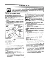
Страница 12: ...emove key Always remove key when leaving tractor to prevent unauthorized use Never use choke to stop engine NOTE Under certain conditions when tractor is standing idle with the engirle running hot engine exhaust gases may cause browning of grass_ To eliminate this possibility always stop engine when stopping tractor on grass areas I CAUTION Always stop tractor com pletely as described above before...

Страница 13: ...AL IS DEPRESSED To restart movement slowly release parking brake and clutch brake pedal Slowly move motion control lever to slowest setting Make all turns slowly TO TRANSPORT See Figs 8 and 11 When pushingortowingyourtractor be sure todisengage transmissionby placingfreewheel control in freewheeling position Free wheel controlis located at the rear drawbar of tractor Raise attachment lift to highe...

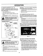
Страница 14: ...EQUIRE REMOVAL FOR SERVtCE OR REPLACEMENT tT SHOULD BE PURGED AFTER REtNSTALLATION BEFORE OPERATING THE TRACTOR Place tractor safely on level surface with engine off and parking brake set Disengage transmission by placing freewheel control in freewheeling position See TO TRANSPORT in this section of manual o Sitting inthe tractor seat start engine After the engine is running move throttle control ...

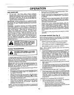
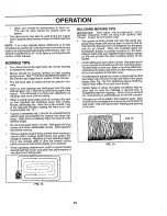
Страница 15: ...ngine at full throttle when mowing to assure better mowing performance and proper dis charge of material Regulate ground speed by select ing a low enough gear to give the mower cutting performance as well as the quality of cut desired When operating attachments select a ground speed that will suit the terrain and give best performance of the attachment being used f 1 IMPORTANT FOR BEST PERFORMANCE...

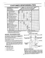
Страница 16: ...ill need to be made periodically to properly maintain your tractor All adjustments in the Service and Adjustments section of this manual should be checked at least once each season Once a year you should replace the spark plug clean or replace air filter and check blades and belts for wear A new spark plug and clean air filter assure proper air fuel mixture and help your engine runbetter andlast l...

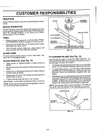
Страница 17: ...act order as shown Tighten bolt securely 30 35 Ft Lbs torque IMPORTANT BLADE BOLT IS GRADE 8 HEATTREATED NOTE We do not recommend sharpening blade but ifyou do be sure the blade is balanced BLADE HEX BOLT GRADE 8 MANDREL TRAILING EDGE A GRADE 8 HEATTREATED BOLT CAN BE IDENTIFIED BYSIXLINES ONTHE BOLT HEADo FIG 14 TO SHARPEN BLADE See Fig 15 Care should be taken to keep the blade balanced An unbala...

Страница 18: ...or 25 hours in one year Check the crankcase oil level before starting the engine and after each eight 8 hours of operation Tighten oil fill cap dipstick securely each time you check the oil Level TO CHANGE ENGINE OIL See Figs 16 and 17 Determine temperature range expected before oil change All oif must meet AP1 sewice classification SFor SG V BELTS Check V belts for deteriorationand wear after 100...

Страница 19: ...entlyonflat surface Ifvery dirty or damaged replace cartndge o Reinstall cartridge nut precleaner cover and secure with knob s IMPORTANT PETROLEUM SOLVENTS SUCH AS KEROSENE ARE NOT TO BE USED TO CLEAN THE CARTRIDGE THEY MAY CAUSE DETERIORATION OF THE CARTRIDGE DO NOT OIL CARTRIDGEo DO NOT USE PRESSURIZED AIR TO CLEAN OR DRY CARTRIDGE COVER KNOB _ COVER __ FOAM __ PRE Ct EANER CARTRIDGE NUT PAPER C...

Страница 20: ...placement is required_ With engine cool remove filter and plug fuet line sections Place new fuel filter in position in fuel line with arrow pointingtowards carburetor Be sure there are no fuel line Ieaks and clamps are properly positioned Immediately wipe up any spilled gasoline CLAMP FUEL FILTER FIG 20 CLEANING Clean engine battery seat finish etc of all foreign matter Keep finishedsurfaces and w...

Страница 21: ...o lower mower to its lowest position Roll belt off engine pulley Disconnect clutch rod from clutch lever by removing retainer spring Disconnect anti sway bar from chassis bracket by removing retainer spring Disconnect suspension arms from rear deck brackets by removing retainer springs Disconnect front links from deck by removing retainer springs Raise lift lever to raise suspension arms Slide mow...

Страница 22: ...ind the mandrel at bottom edge of mower housing as shown If adjustment is necessary make adjustment on one side of mower only To raise one side of mower tighten lift iinkadjustment nut on that side To lower one side of mower loosen lift link adjustment nut on that side NOTE Each full turn of adjustment nut wil change mower height about 1 8 Recheck measurements after adjusting BOTTOM EDGE BOTTOM ED...

Страница 23: ...distance becomes 1 3 4 L Retighten jam nut against nut A o Road test tractor for proper stopping distance as stated above Readjust if necessary If stopping distance is still greater than six 6 feet in highest gear further maintenance is necessary Contact your nearest au thorized service center department WITH PARKING BRAKE ENGAGED NUT A NUT ARM DO NOTTOUCH THIS NUT IF FURTHER BRAKE ADJUSTMENTIS NE...

Страница 24: ...ct the front wheel toe in or camber contact your nearest authorized service center department TO REMOVE WHEEL FOR REPAIRS See Fig 30 Block up axle securely Remove axle cover retaining ringand washersto allow wheel removal rear wheel contains a square key Do not lose Repair tire and reassembte_ On rear wheels only align grooves in rear wheel hub and axleo Insert square key Replace washers and snap ...

Страница 25: ...BLY See Fig 32 Raise hood_ Unsnap headlight wire connector Stand infront of tractor Grasp hood at sides tilttoward engine and lift off of tractor To replace reverse above procedures __ _ _ HOOD FIG 32 ENGINE TO ADJUST THROTTLE CONTROL CABLE See Fig 33 The throttle control has been preset at the factory and adjustment should not be necessary Check adjustment as described below before loosening cabl...

Страница 26: ... fast 4 position If engine hesitates or dies turn idle mixture valve out counterclockwise 1 8 turn Repeattest and continue to adjust if necessary until engine acceler ates smoothly High speed stop is factory adjusted Do not adjust damage may result IMPORTANT NEVER TAMPER WITH THE ENGINE GOVERNOR WHICH IS FACTORY SET FOR PROPER ENGINE SPEED OVERSPEEDING THE ENGINE ABOVE THE FACTORY HIGH SPEED SETTI...

Страница 27: ...ENT GUM DEPOSITS FROM FORMING IN ESSENTIAL FUEL SYSTEM PARTS SUCH AS CARBURETOR FUEL FILTER FUEL HOSE OR TANK DURING STORAGE ALSO EXPERIENCE INDICATES THAT ALCOHOL BLENDED FUELS CALLED GASOHOL OR USING ETHANOL OR METHANOL CAN ATTRACT MOISTURE WHICH LEADS TO SEPARATION AND FORMATION OF ACIDS DURING STORAGE ACIDIC GAS CAN DAMAGE THE FUEL SYSTEM OF AN ENGINE WHILE IN STORAGE Drain the fuel tank Start...

Страница 28: ...tion section 3_ Wait several minutes before attempting to start 4 Reptace spark plug 5 Cleardreplaee air filter 6 Replace fuel filler 7 Drain fuel tank and carburetor refill tank with fresh gasoline and replace fuel filter B Check all wiring 9 See To Adjust Carburetor in Service Adjustments section 10 Contact an authorized service centertdepartment 1 Clean replace air filter 2 Replace spark plug 3...

Страница 29: ...L 3 Faulty light switch 4 Loose or damaged widng 5 Blown fuse 1 Bad battery ceil s 2 Poor cable connections 3 Faulty regulator If so equipped 4 Faulty alternator 1 Engine throttlecontrol not set at SLOW position for 30 seconds before stopping engine CORRECTION i lllll uiill t Check wiring switches and connections If not corrected contact an authorized service centart department I Replace blade Tig...

Страница 30: ...SERVICE NOTES 30 ...

Страница 31: ...ANGE IGNITION SWITCH POSITION CIRCUIT MAKE OFF G M L NONE RUN LIGHT B L A Y RUN B L NONE 1 START B L S NONE NOTE YOUR TRACTOR IS EQUIPPED WITH A SPECIAL ALTERNATOR SYSTEM_ THE LIGHTS ARE NOT CONNECTED TO THE BATTERY BUT HAVE THEIR OWN ELECTRICAL SOURCE BECAUSE OF THIS THE BRIGHTNESS OF THE LIGHTS WILL CHANGE WITH ENGINE SPEED AT IDLE THE LIGHTS WILL DIM AS THE ENGINE IS SPEEDED UP THE LIGHTS WILL ...

Страница 32: ...REPAIR PARTS TRACTOR MODEL NUMBER 917 258530 ELECTRICAL I aT_Jr_ 21 32 19 26 I I t I 6 i t I 32 ...

Страница 33: ...Bolt Hex Head 1 4 20 unc x 3 4 Washer Washer Nut Tube Plastic 12 Case Battery Mech Hinge Clamp Hose Switch nterlock Push In Washer Lock Nut Hex Jam 1 4 20 UNC Harness Light Socket includes 4152J Bulb Light Cable Battery 6 Gauge Red 11 Cable Battery 6 Gauge Red W 16 Wire Fuse 30 Amp Cable Ground 6 Gauge Black 12 Switch Plunger Switch Ignition Nut ignition Cover Key Switch Key Ignition Harness Ignit...

Страница 34: ...REPAIR PARTS TRACTOR MODEL NUMBER 917 258530 CHASSIS AND ENCLOSURES 28 12 6O 3 3 74 38_3 _ 39 14 34 ...

Страница 35: ...mper Hood Dash Dash Bolt Carriage 3 8 16 x 3 4 Panel Dash L H Clip Tinnerman Grille P L Panel Dash R H Screw Thdrol 3 8 16 x 1 2 Hood Assembly Bumper Hood Washer t3 32 x 13 16 x 12 Gauge Nut Grille wlClips MS 558 Lens Grille Fend Ftrest Pnt BTLT N HLD 558 Bracket Fender Support Pivot Bracket Assembly L Ho Pivot Bracket Assembly R H Nut Lock wltnsert 1 4 20 UNC Washer 9 32 x 7 8 x 16 Ga Bracket Gri...

Страница 36: ...REPAIR PARTS TRACTOR MODEL NUMBER 917 258530 DRIVE 57 J 77 15 97 _ 98 30 24 26 62 12 36 32 22 61 105 37 84100 10o 27 106 36 ...

Страница 37: ...7 127783 Pulley Idler V Groove 98 73510600 48 154604 BeNcrankAssembly Clutch 100 19111216 49 123205X Retainer Belt 102 141322 50 STD523715 Bolt t03 73940800 51 STD541437 Nut Crownlock 3 8 16 UNC 104 140156 52 STD54143I Nut Crownlock 5 16 18 Unc 105 71070516 53 105710X Link Clutch 106 74780520 55 t05709X Spring Return Clutch 116 72110610 56 STD523712 Bolt Hex 3 8 16 x 1 1 4 118 154774 57 140294 V B...

Страница 38: ...REPAIR PARTS TRACTOR MODEL NUMBER 917 258530 STEERING ASSEMBLY _41 i L 62 J 29 27 J 11 40 25 47 28 3O 32 67 43 38 ...

Страница 39: ... Washer 27 32 x 1 1 4 x 16 Gauge Ring Klip Bearing Steering Column Draglink Extended Stamped Washer Lock Bearing Axle STLT GT Nut Lock Flange 5 8 11 UNC Pin Axle 5 8 x 1 55 1 54 Shaft Assembly Steering Washer Thrust 515 x 750 x 033 Support Shaft Washer Shim 1 4 x 5 8 x 062 Washer Screw Hex Socket Head 1 4 20 x 5 8 Pittman Shaft Assembly Bracket Steering Bushing Link Drag Gear Sector Washer 13 32 x...

Страница 40: ...ged Nut Spring Seat Screw Thd Roll 3 8 16 x 1 Washer 13 32 x 1 x 14 Gauge Pan Seat Emboss QCK Conn Bracket Switch Mounting Bushing Snap Bolt Carriage 1 4 20 x 1 3 8 15 134300 16 121250X 17 123976X 21 153236 22 STD541431 23 74780814 24 19171912 25 127018X 26 STD551150 Spacer Split _28x 88 Spring Locknut Flange 1 4 Grade 5 Bolt Shoulder 5 16 t8 UNC Nut Bolt Hex Head Fin 1 2 13 x7 8 Grade 5 Washer 17...

Страница 41: ...PTION Decal Chassis 6 Speed 42 Decal V Belt Schematic Decal Ins Hood Decal Battery Dngr Psn Eng Decal Fender Auto Decal Lift Handle Decal Drawbar Cntrl Mvt Hyd LT Pad Footrest LH STLT Pad Footrest RH STLT Owner s Manual English Owner s Manual Spanish WHEELS TIRES 2 _ 5 8 7 4 10 1I 41 KEY PART NO NO DESCRIPTION 1 59192 Valve Cap Tire 2 65139 Stem Valve 3 106222X Tire Front 4 59904 Tube Front Tire N...

Страница 42: ...REPAIR PARTS TRACTOR MODEL NUMBER 917 258530 ENGINE 3 81 31 4O 38 78 33 r 37 _ 3 _ _9 _ _ 23 29 OPTIONAL EQUIPMENT Spark Arrester 35 42 ...

Страница 43: ...x 5 8 Engine See Breakdown Briggs Model 28N707 0173 01 Muffler Gasket Exhaust Nipple Pipe 3t8 NPT x 3 Elbow Standard 90 3 8 18 NPT Washer Shield Heat Arrestor Spark Tank Fuel Cap Assembly Fuel Tank Vented Clamp Hose Screw Thdrol 5 16 18 x 3 4 Tyt Line Fuel Plug Oil Drain Order From Engine Manufacturer Bushing Snap Fuel Line Screw Hex Washer Head Thd Roll 1 4 20 x 3 4 Washer 9 32 x 7 8 x 16 Gauge W...

Страница 44: ...REPAIR PARTS TRACTOR MODEL NUMBER 917 258530 MOWER LIFT 28 27 26 24 23 13 4 19 13 32 32 5 13 19 49 2O 15 7 6 5 161718 20 20 15 44 ...

Страница 45: ...g 15 127218 Link Front 16 73350800 Nut Hex Jam 1 2 13 UNC 17 130171 Trunnion 18 73800800 Locknut Hex with Washer Insert 1 2 13 UNC 19 139868 Arm Suspension Rear 20 STD624008 Retainer Spring 23 110807X Nut Special 24 19131016 Washer 13 32 x 5 8 x 16 Gauge 25 2876H Spring 26 76020308 Pin Cotter 3 32 x 1 2 27 126971X Rod Adjust Lift 28 73350600 Nut Hex Jam 3 8 16 UNC 29 138057 Knob Infinite Height Ad...

Страница 46: ...REPAIR PARTS TRACTOR MODEL NUMBER 917 258530 MOWER DECK 76 53 58 35 113 111 114 116 _f I _p_7 _129 92_ _ 3 _ 92 19 _ 21 2 16 34 33 32 18 13_ 9 _ 02 105 _ 104 106 27 46 ...

Страница 47: ...ock 3 8 16 UNC 129 Rod Pivot with Nibs 130 Rod Clutch Secondary with Nibs 131 Guard Mandrel Loll 132 Retainer Screw Thd Roll 1 4 20 x 5 8 Washer Hardened Roller Assembly Cam Follower Bolt Shoulder 10 24 Grade 5 Locknut Bolt Shoulder 5 16 18 UNC Arm Assembly Pad Brake Washer Hardened Arm Idler Spacer Retainer 140086 141043 149846 144200 142427 131870 127847 121748X 12O00029 1289O3 127845 154809 127...

Страница 48: ...REPAIR PARTS TRACTOR MODEL NUMBER 917 258530 HYDRO GEAR TRANSAXLE MODEL NUMBER 310 0650 58 19 23 43 26 27 90 _3 52 91 9 69 17 t4 4 5 3 35 _13 48 ...

Страница 49: ...24 17 142941 Guide Slot 83 142971 Jackshaft Assembly 18 150772 Shaft Motor 85 150806 Jackshaft 19 150773 Bearing Thrust 42 x 68 x t6 88 142973 Screw Cap 23 142944 Block Cy fnder Assembly 89 142974 Washer 7 16 x I x t 2 24 142945 Seal Lip 10 x 25 x 7 90 142975 Sleeve Bearing 25 142946 Actuator Bypass 91 142976 Seaf Wiper 26 150774 Center Section Assembly Kit 92 t42977 Spring Block 27 142948 Sea Lip...

Страница 50: ... NUMBER 917 258530 BRIGGS STRATTON ENGINE MODEL NUMBER 28N707 TYPE NUMBER 0173 01 9 230 _614 230 634A 4O 635 337 868A 166 294 1029 1022 1034 1026 50 562 45 h REQUIRES SPECIAL TOOLS TO INSTALL SEE REPAIR INSTRUCTION MANUAL 7 1023 ...

Страница 51: ...EL NUMBER 917 258530 BRIGGS STRAI I ON ENGINE MODEL NUMBER 28N707 TYPE NUMBER 0 173 0 1 127 138 106 987 95 117 634 634B 137 1_47 52 REQUIRES SPECIAL TOOLS TO INSTALL SEE REPAIR INSTRUCTION MANUAL 52 1033 VALVE OVERHAUL KIT 51 ...

Страница 52: ... 917 258530 BRIGGS STRATTON ENGINE MODEL NUMBER 28N707 TYPE NUMBER 0173 01 3 20 634A 842 524 868 868A 358 GASKET SET 363 1 138 137 i 1 iiii lUl II IlUll _ 977 CARBUREI OR GASKET SET 304 668 305_ 468 1006 78 467 171 _224 334 535 445 52 ...

Страница 53: ...REPAIR PARTS TRACTOR MODEL NUMBER 917 258530 BRIGGS STRATTON ENGINE MODEL NUMBER 28N707 TYPE NUMBER 0173 01 209 77_ _ 601 783 801 311 803 1090 53 ...

Страница 54: ... Connecting 230 020 Undersize Crankpin Bore 232 Screw Hex Washer Head 1 57 64 238 Screw Hex Washer Head 1 5 8 240 Valve Exhaust 265 Valve Intake 284 Spring Valve Guard Flywheel Retainer Valve Spring Tappet Valve Gear Cam Gasket Carburetor Carburetor to Elbow Also Included in Gasket Set Part Number 495993 Gasket Carburetor Etbow to Cylinder ud Carburetor Mounting Washer Spring Screw Pan Head 94098 ...

Страница 55: ...4439 Screen Flush Rotating 977 494385 Carburetor Gasket Set 474 393474 Stator Alternator 987 281166 Seal Throttle Shaft 482 93621 Screw Sems I005 281400 Fan Flywheel 510 497606 Drive Starter 1006 224413 Retainer Fan 523 495230 Cap and Dipstick Oil Filler 1019 496758 Label Kit 524 68838 Seal Filler Tube 1022 272475 Gasket Cover 525 496113 Tube Oil Filler 1023 224552 Cover Rocker Arm 535 272403 Elem...

Страница 56: ...i llll ill i i illlll ii ii illl illll illlllll ii ii i SERVICE NOTES iiii III IIIlUll I III i iiiii II IIII i ii ii ii iHi i i llllll i i ill ii illll ii illl ii ii ill 56 ...

Страница 57: ... ii_l iillllllllllll i i ii ii IH H HHH I I H IlllH Illllll Illll I IL I SERVICE NOTES 57 ...

Страница 58: ... illlllll i illllllll i i i iiill E NOTES II III IIIII I I IIIIII II II IIII IIIII I 58 ...

Страница 59: ... HOLD THIS LEVEL WITH SKY LINE OR TREE 15 MAX IIHI Illlllllllllll Illll III II III _ Operate your Tractor up and down the face of slopes not _ _ greater than 15 never across the face Make turns gradu J _1 _ ally to prevent tipping or loss of control Exercise extreme caution when changing direction on slopes ...

Страница 60: ...ted under the seat The model number for your engine wilt be found on the blower housing of the engine All parts listed herein may be ordered from any Sears Roebuck and Co Service Center Department and most Re tail Stores_ WHEN ORDERING REPAIR PARTS ALWAYS GIVE THE FOLLOWING INFORMATION PRODUCT TRACTOR MODEL NUMBER 917 258530 ENGINE MODEL NO 28N707 TYPE NO 0173 01 PART NUMBER PART DESCRIPTION Your ...

Отзывы: