


5
ASSEMBLY
CARTON CONTENTS
Check carton contents against the fol-
lowing list.
Model C944.512200
S
Trimmer
S
Shield
Examine parts for damage. Do not
use damaged parts.
NOTE: If you need assistance or find
parts missing or damaged, call
1-800-235-5878.
ASSEMBLY
WARNING:
If received as-
sembled, review all assembly steps to
ensure your unit is properly as-
sembled and all fasteners are secure.
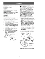
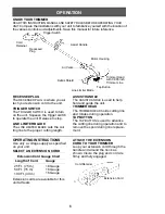
ATTACHING ASSIST HANDLE
1. Place unit on a flat surface.
2. Loosen and remove wing nut and
bolt from assist handle.
3. Firmly push the assist handle over
the tube. To make installation eas-
ier, tilt handle toward trigger hous-
ing while pushing down (see il-
lustration).
4. Reinstall bolt in handle. Thread
wing nut onto bolt.
5. Adjust the handle up or down the
tube to a comfortable position;
tighten wing nut securely.
Assist handle
Tube
Trigger
Housing
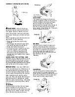
ATTACHING THE SHIELD
WARNING:
The shield must be
properly installed. The shield provides
partial protection from the risk of
thrown objects to the operator and
others. Your unit is equipped with a
line limiter blade, which cuts excess
line to the proper length while running.
The line limiter blade (on underside of
shield) is sharp and can cut you.
NOTE: If shield is not properly
installed, damage to unit (including
motor failure) will result.
1. Align the installation arrow on the
shield with the installation arrow on
the motor housing (see illustration
below).
2. Insert the shield onto the motor
housing. Ensure the cutting head
remains free to rotate and the line
is not caught between the shield
and the motor housing.
3. Twist the shield as illustrated until
it snaps securely into place. Make
sure the shield is assembled to the
unit as shown on the front cover of
this manual.
CAUTION:
Sharp line limiter blade
ALIGN INSTALLATION ARROWS
Twist shield
in direction of
arrow to
assemble


