


11
English
Removing The Chuck (Fig. M)
1. Turn the feed handles to lower the chuck to the lowest
position.
2. Place a ball joint separator (not shown) above the chuck
and tap it lightly with a hammer or rubber mallet to
cause the chuck to drop from the spindle.
CAUTION:
Never hit the chuck directly with the
hammer or rubber mallet.
CAUTION:
To avoid possible damage to the chuck,
raise the jaws all the way first and be prepared to
catch the chuck as it falls.
Chuck Key Storage (Fig. N)
Storage holder
23
for the chuck key
37
is located on the
right side of the drill press.
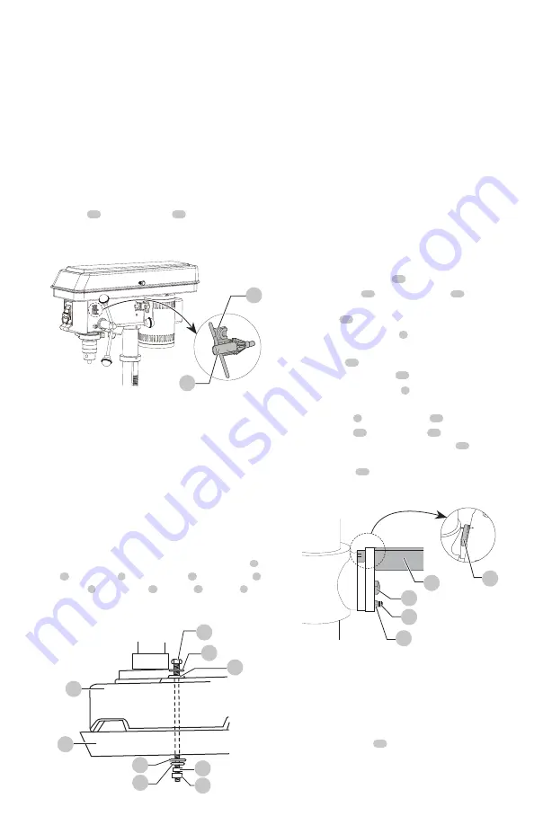
Mounting Drill Press To Work Surface (Fig. O)
WARNING:
The drill press must be securely fastened
by the two base holes to a stand with heavy-duty
fasteners. This will prevent the drill press from tipping
over, sliding, or walking during operation.
1. If mounting the drill press to a workbench, a solid wood
bench is preferred over a plywood board, to reduce
noise and vibration.
2. Holes should be pre-drilled through the supporting
surface.
3. The hardware to mount this drill press is NOT supplied
with the tool. The hardware used are: drill press base
a
,
bolt
b
, flat washer
c
, rubber washer
d
, work surface
e
,
flat washer
f
, lock washer
g
, hex nut
h
, jam nut
i
.
Fig. N
23
37
Fig. O
b
c
d
a
e
h
i
f
g
Adjustments Instructions
nOTE:
All the adjustments for the operation of the drill
press have been completed at the factory. Due to normal
wear and use, some occasional readjustments may be
necessary.
WARNING:
To avoid injury from an accidental
start, ALWAYS make sure the switch is in the “OFF”
position, the switch key is removed, and the plug is not
connected to the power source outlet before making
adjustments.
Bevel Drilling (Fig. P)
WARNING:
To prevent personal injury, always
disconnect the plug from the power source when
making any adjustments.
nOTE:
A bevel scale has been included to measure
approximate bevel angles. If precision is necessary, a square
or other measuring tool should be used to position the
table. To use the bevel scale
38
:
1. TIGHTEN the nut
39
on the locking pin
40
using a
10 mm or adjustable wrench clockwise to RELEASE the
locking pin
40
from the table support.
2. Loosen the bevel lock bolt
3
using a 19 mm or
adjustable wrench.
3. Tilt the table
20
to desired bevel angle that will be
shown on the bevel scale
38
.
4. Tighten the bevel lock bolt
3
.
5. To return the table to horizontal position, loosen the
bevel lock bolt
3
, return the table
20
to the 0° position.
6. Return the nut
39
on locking pin
40
to the OUTSIDE
END OF THREADS. Gently tap locking pin
40
until it is
seated in the mating hole of the table bracket. Hand
tighten the nut
39
.
Spindle / Quill (Fig. Q)
Rotate the feed handles counterclockwise to lower spindle
to its lowest position. Hold the chuck and move it front to
back. If there is excessive play, proceed with the following
adjustments:
1. Loosen the lock nut
41
located on the right side of the
drill press by using a 13 mm wrench.
Fig. P
38
39
40
3
20


