background image

Chute Assembly 

Refer to the Assembly & Set-up section for instructions on 

adjusting the chute assembly.

Skid Shoes

Refer to the Assembly & Set-up section for instructions on 

adjusting the skid shoes.

Drive Control

When the drive control is released and in the disengaged “up” 

position, the cable should have very little slack. It should NOT be 

tight. 

NOTE: 

If excessive slack is present in the drive cable or if the snow 

thrower’s drive is disengaging intermittently during operation, 

the cable may be in need of adjustment.
Check the adjustment of the drive control as follows:
1. 

With the drive control released, push the snow thrower 

gently forward. The unit should roll freely. 

2. 

Engage the drive control and gently attempt to push the 

snow thrower forward. The wheels should not turn. The 

unit should not roll freely.

3. 

With the drive control released, move the shift lever back 

and forth between the R2 position and the F6 position 

several times. There should be no resistance in the shift 

lever.

If any of the above tests failed, the drive cable is in need of 

adjustment. Proceed as follows:
1. 

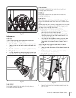
Loosen the lower hex screw on the drive cable bracket. See 

Fig. 6-5.

2. 

Position the bracket upward to provide more slack (or 

downward to increase cable tension). 

3. 

Retighten the upper hex screw.

4. 

Repeat Drive Control Test to verify proper adjustment has 

been achieved.

Fig. 6-5

Adjustments

Shift Cable

If the full range of speeds (forward and reverse) cannot be 

achieved, adjust the shift cable as follows:
1. 

Place the shift lever in the fastest forward speed position.

2. 

Loosen the hex  nut on the shift cable index bracket. See 

Fig. 6-4.

3. 

Pivot the bracket downward to take up slack in the cable. 

4. 

Retighten the hex nut.

5. 

If further adjustment is necessary move the shift cable to 

one of the alternate holes in the shift cable index bracket.

Auger Control

Refer to the Assembly & Set-up section for instructions on 

adjusting the auger control cable.

Fig. 6-4

Fig. 6-3

17

S

ection

 6 — M

aintenance

 & a

djuStMentS

Содержание C459-52413

Страница 1: ...ollow all safety rules and operating instructions Operator s Manual SAFETY ASSEMBLY OPERATION MAINTENANCE PARTS LIST PRINTED IN U S A FOR CUSTOMER ASSISTANCE CALL 1 800 668 1238 769 09968 06 11 14 TWO STAGE SNOW THROWERS Model Nos C459 52413 24 C459 52415 28 ...

Страница 2: ... this Operator s Manual may cover a range of product specifications for various models Characteristics and features discussed and or illustrated in this manual may not be applicable to all models The manufacturer reserves the right to change product specifications designs and equipment without notice and without incurring obligation If you have any problems or questions concerning the machine phon...

Страница 3: ...he eyes 2 Do not operate without wearing adequate winter outer garments Do not wear jewelry long scarves or other loose clothing which could become entangled in moving parts Wear footwear which will improve footing on slippery surfaces 3 Use a grounded three wire extension cord and receptacle for all machines with electric start engines 4 Adjust auger housing height to clear gravel or crushed rock...

Страница 4: ...place and working 5 Never run an engine indoors or in a poorly ventilated area Engine exhaust contains carbon monoxide an odorless and deadly gas 6 Do not operate machine while under the influence of alcohol or drugs 7 Muffler and engine become hot and can cause a burn Do not touch Keep children away 8 Exercise extreme caution when operating on or crossing gravel surfaces Stay alert for hidden haz...

Страница 5: ...w minutes to clear snow from machine and prevent freeze up of auger impeller 10 Never store the machine or fuel container inside where there is an open flame spark or pilot light such as a water heater furnace clothes dryer etc 11 Always refer to the operator s manual for proper instructions on off season storage 12 Check fuel line tank cap and fittings frequently for cracks or leaks Replace if ne...

Страница 6: ...et near rotating parts in the auger impeller housing or chute assembly Contact with the rotating parts can amputate hands and feet WARNING THROWN OBJECTS This machine may pick up and throw objects which can cause serious personal injury WARNING GASOLINE IS FLAMMABLE Allow the engine to cool at least two minutes before refueling WARNING CARBON MONOXIDE Never run an engine indoors or in a poorly ven...

Страница 7: ...erenced or engines pictured in this manual are applicable to all snow thrower models NOTE For models with electric start the extension cord is fastened with a cable tie to the rear of the auger housing for shipping purposes Cut the cable tie and remove it before operating the snow thrower Handle Assembly 1 Place the shift lever in the Forward 6 position 2 Observe the lower rear area of the snow th...

Страница 8: ...nion gear faces upward See Fig 3 7 NOTE The joystick will be angled slightly to the right at the one o clock position See Top View in Fig 3 6 NOTE The pinion gear is located on the front of the unit below the control panel 3 Place chute onto chute base with the chute control rod positioned under the handle panel Reinstall the hex bolt previously removed but do not secure with wing nut at this time...

Страница 9: ... up with the closest hole in the chute rotation assembly and insert the cotter pin See Fig 3 9 NOTE The second hole is used to achieve further engagement of the chute control rod into the pinion gear if required refer to Chute Control Rod in the Maintenance and Adjustment section Fig 3 8 Fig 3 9 8 Finish securing chute rotation assembly to chute support bracket with wing nut clevis pin and cotter ...

Страница 10: ...ssure is to be maintained at all times for performance purposes Adjustments Skid Shoes The snow thrower skid shoes are adjusted upward at the factory for shipping purposes Adjust them downward if desired prior to operating the snow thrower CAUTION It is not recommended that you operate this snow thrower on gravel as it can easily pick up and throw loose gravel causing personal injury or damage to ...

Страница 11: ...or the first time and at the start of each winter Check the adjustment of the auger control as follows 1 When the auger control is released and in the disengaged up position the cable should have very little slack It should NOT be tight 2 In a well ventilated area start the snow thrower engine as instructed in the separate engine manual 3 While standing in the operator s position behind the snow t...

Страница 12: ...ion the skid shoes based on surface conditions Adjust upward for hard packed snow Adjust downward when operating on gravel or crushed rock surfaces Augers When engaged the augers rotate and draw snow into the auger housing Chute Assembly Snow drawn into the auger housing is discharged out the chute assembly Headlight if so equipped The headlight is on whenever the engine is running Fig 4 1 Drive C...

Страница 13: ...re to do so will result in increased wear on your machine s drive system Steering Trigger Controls if so equipped The left and right wheel steering trigger controls are located on the underside of the handles Squeeze the right control to turn right Squeeze the left control to turn left CAUTION Operate the snow thrower in open areas until you are familiar with these controls Chute Clean Out Tool WA...

Страница 14: ...e of the dash panel To change the direction in which snow is thrown squeeze the button on the joy stick and pivot the joy stick to the right or to the left To change the angle distance which snow is thrown pivot the joy stick forward or backward 14 Section 4 Controls and Features ...

Страница 15: ...al interlock mechanism only NOTE This drive lever also locks auger control so you can turn the chute control without interrupting the snow throwing process 3 Release the auger control the interlock mechanism should keep the auger control engaged until the drive control is released 4 Release the drive control to stop both the augers and the wheel drive To stop the auger both levers must be released...

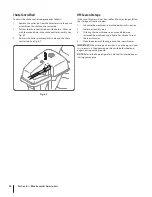
Страница 16: ...Gear Shaft The gear hex shaft should be lubricated at least once a season or after every twenty five 25 hours of operation 1 Allow the engine to run until it is out of fuel 2 Carefully pivot the snow thrower up and forward so that it rests on the auger housing 3 Remove the frame cover from the underside of the snow thrower by removing the self tapping screws which secure it Refer to Fig 7 4 4 Appl...

Страница 17: ... the R2 position and the F6 position several times There should be no resistance in the shift lever If any of the above tests failed the drive cable is in need of adjustment Proceed as follows 1 Loosen the lower hex screw on the drive cable bracket See Fig 6 5 2 Position the bracket upward to provide more slack or downward to increase cable tension 3 Retighten the upper hex screw 4 Repeat Drive Co...

Страница 18: ... be used for 30 days or longer follow the storage instructions below 1 Lubricate the machine as instructed earlier in this section 2 Store in a clean dry area 3 If storing the snow thrower in an unventilated area rustproof the machine using a light oil or silicone to coat the snow thrower 4 Clean the exterior of the engine and the snow thrower IMPORTANT When storing unit or when it is not being se...

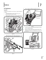
Страница 19: ...e by removing the two self tapping screws See Fig 7 1 3 Loosen and remove the two bolts and flat washers securing the belt guide See Figure 7 2 Remove belt guide 4 Roll the auger belt off the engine pulley See Fig 7 3 5 Carefully pivot the snow thrower up and forward so that it rests on the auger housing 6 Remove the frame cover from the underside of the snow thrower by removing the self tapping s...

Страница 20: ...1 of the Assembly and Set Up section Drive Belt To remove and replace your snow thrower s drive belt proceed as follows 1 To prevent spillage remove all fuel from tank by running engine until it stops Do not attempt to pour fuel from the engine 2 Remove the plastic belt cover on the front of the engine by removing the two self tapping screws Refer to Fig 7 1 3 Remove the belt as follows See Fig 7 ...

Страница 21: ...rd so that it rests on the auger housing 3 Remove the frame cover from the underside of the snow thrower by removing the self tapping screws which secure it See Fig 7 9 4 Examine the friction wheel for signs of wear or cracking Friction Wheel Removal For units not equipped with Steering Trigger Controls If the snow thrower fails to drive with the drive control engaged and performing the drive cont...

Страница 22: ...ure the friction wheel s side plates together See Fig 7 12 2 Remove the rubber ring from between the plates 3 Reassemble the side plates with a new rubber ring NOTE When reassembling the friction wheel assembly make sure that the rubber ring is centered and seated properly between the side plates Tighten each screw only one rotation before turning the wheel clockwise and proceeding with the next s...

Страница 23: ...oose 2 Gas cap vent hole plugged 1 Connect and tighten spark plug wire 2 Remove ice and snow from gas cap Be certain vent hole is clear Unit fails to propel itself 1 Drive control cable in need of adjustment 2 Drive belt loose or damaged 3 Friction wheel worn 1 Adjust drive control cable Refer to Maintenance Adjustments section 2 Replace drive belt Refer to Service section 3 Replace friction wheel...

Страница 24: ...de Shoe Standard Steel 731 06439 Slide Shoe Standard Polymer 790 00091 Slide Shoe Deluxe Steel 731 05984A Slide Shoe Deluxe Polymer 731 06931 Slide Shoe Deluxe Blue Polymer 931 2643 Chute Clean out Tool 790 00120 Shave Plate 24 790 00121 Shave Plate 26 790 00118 Shave Plate 28 790 00119 Shave Plate 30 951 10630 Key NOTE Download a complete Parts Manual refer to customer support on page 2 Be sure t...

Страница 25: ... normal deterioration of the exterior finish due to use or exposure d Service completed by someone other than an authorized service dealer e MTD does not extend any warranty for products sold or exported outside of Canada including possessions and territories f Replacement parts that are not genuine MTD parts g Transportation charges and service calls h If products are used commercially MTD may se...

Страница 26: ...0 668 1238 or at http www mtdcanada com GENERAL EMISSIONS WARRANTY COVERAGE MTD Consumer Group Inc warrants to the ultimate purchaser and each subsequent purchaser that the outdoor equipment is 1 designed built and equipped so as to conform with all applicable regulations and 2 free from defects in materials and workmanship that cause the failure of a warranted part for a period of two years The w...

Страница 27: ... replacement of the part That notwithstanding any adjustment of a component that has a factory installed and properly operating adjustment limiting device is still eligible for warranty coverage Further the coverage under this warranty extends only to parts that were present on the off road equipment purchased The following emission warranty parts are covered if applicable 1 Fuel Metering System C...

Страница 28: ...28 Notes ...

Страница 29: ...28 Notes ...

Страница 30: ...tuation tout ajuste ment d une pièce équipée d un dispositif de limitation correctement installé et en bon état de fonctionnement demeure admissible à la garantie De plus cette garantie se prolonge seulement aux pièces qui étaient présentes sur le moteur hors route et sur l équipement acheté 1 Système de dosage du carburant Système d enrichissement du carburant pour démarrages à froid Carburateur ...

Страница 31: ... http www mtdcanada com PROTECTION OFFERTE PAR LA GARANTIE CONCERNANT LES ÉMISSIONS MTD Consumer Group Inc garantit à l acheteur au détail initial et à chaque acheteur successif 1 que la machine a été conçue construite et équipée conformément à tous les règlements applicables et 2 qu elle est exempte de tout vice de matière et de fabrication susceptible de causer la défaillance d une pièce garanti...

Страница 32: ... ou du plateau de coupe et la détérioration normale de la finition du fait de l utilisation de la machine ou de son exposition aux intempéries d L entretien ou les réparations effectués par quiconque autre qu une station technique agréée e MTD ne garantit pas les produits vendus ou exportés du Canada de ses possessions et territoires f Les pièces de rechange si elles ne sont pas des pièces MTD aut...

Страница 33: ...rie Acier 731 06439 Patin de série Polymer 790 00091 Patin de luxe Acier 731 05984A Patin de luxe Polymer 731 06931 Patin de luxe bleu Polymer 931 2643 Outil de dégagement de la goulotte 790 00120 Lame de raclage 24 po 790 00121 Lame de raclage 26 po 790 00118 Lame de raclage 28 po 790 00119 Lame de raclage 30 po 951 10292 Clé REMARQUE Vous pouvez télécharger un livret contenant la liste complète ...

Страница 34: ...happement d aération bouché 1 Branchez et serrez le fil de la bougie 2 Dégagez la glace et la neige du chapeau Assurez vous de la propreté d aération La souffleuse n avance pas 1 Câble d entraînement mal réglé 2 Courroie d entraînement abîmée ou ayant du jeu 3 La roue de frottement est usée 1 Réglez le câble d entraînement Voir le Réglages 2 Remplacez la courroie d entraînement 3 Remplacez la roue...

Страница 35: ...Entretien et réglages Si vous démontez la roue de frottement et ne remplacez que la bague en caoutchouc procédez comme suit 1 Enlevez les quatre vis qui maintiennent les plaques latérales de la roue de frottement Voir la Fig 7 12 2 Retirez la bague en caoutchouc qui se trouve entre les plaques 3 Remontez les plaques latérales avec une bague en caoutchouc neuve REMARQUE Pour remonter la roue de fro...

Страница 36: ... verser l essence du moteur 2 Basculez doucement la souffleuse vers l avant pour la faire reposer sur l habitacle de la tarière 3 Démontez le couvre châssis du dessous de la souffleuse en retirant les quatre vis auto taraudeuses qui le maintiennent en place Voir la Fig 7 9 4 Examinez soigneusement la roue de frottement pour détecter tout signe d usure ou de fendillement Démontage de la roue de fro...

Страница 37: ...1 du chapitre Assemblage et montage Courroie de transmission Pour démonter et remplacer la courroie de transmission de la souffleuse procédez comme suit 1 Laissez le moteur tourner jusqu à ce qu il tombe en panne d essence N essayez pas de verser l essence du moteur 2 Retirez le couvre courroie en plastique sur le devant du moteur en enlevant les deux vis auto taraudeuses Voir la Fig 7 1 3 Dégagez...

Страница 38: ...enlevant les deux vis auto taraudeuses Voir la Fig 7 1 3 Retirez le protecteur de la courroie de fil en enlevant les deux boulons à tête hexagonale et les rondelles plates Voir Figure 7 2 4 Dégagez la courroie de la tarière de la poulie motrice Voir la Fig 7 3 5 Basculez doucement la souffleuse vers l avant pour la faire reposer sur l habitacle de la tarière 6 Démontez le couvre châssis du dessous...

Страница 39: ...re entreposé pendant plus de 30 jours préparez le de la façon selon les instructions fournies dans la notice d utilisation du moteur qui accompagne votre souffleuse Consultez la notice d utilisation du moteur Enlevez tout les débris sur l extérieur de la souffleuse Suivez les renseignements de lubrification à la page 16 Entreposez la souffleuse dans un endroit sec et propre Prenez soin avant de re...

Страница 40: ...ent 3 Débrayez la commande de la transmission déplacez plusieurs fois le levier de vitesses d avant en arrière entre les positions R2 et F6 Vous ne devez sentir aucune résistance dans le levier de vitesses Si l un des tests ci dessus échoue ajustez le câble de la transmission Continuez comme suit 1 Desserrez le vis à six pans inférieur sur le support du câble de la transmission Voir la Fig 6 5 Fig...

Страница 41: ...la lame plate neuve en vérifiant que la tête des boulons ordinaires se trouve à l intérieur de l habitacle Serrez à fond Lubrification Arbre de transmission Lubrifiez l arbre de transmission hex au moins une fois par saison ou toutes les 25 heures d utilisation 1 Laissez tourner le moteur jusqu à ce qu il tombe en panne d essence 2 Basculez doucement la souffleuse vers l avant pour la faire repose...

Страница 42: ...dèles équipés avec le mécanisme de blocage en option REMARQUE Cette même poignée permet de bloquer la commande de la tarière pour permettre au conducteur puisse orienter la goulotte sans cesser de projeter la neige 3 Débrayez la commande de la tarière le mécanisme de blocage maintient la tarière engagée jusqu à ce que la commande de la transmission soit débrayée 4 Lâchez la commande de la transmis...

Страница 43: ...Pour modifier l angle la distance de projection de la neige poussez le levier de commande vers l avant ou tirez le vers l arrière Pour tourner la souffleuse vers la droite ou vers la gauche pressez sur la commande correspondante de la direction des roues COMMANDE DE LA GOULOTTE BOUTON POUSSOIR BOUTON POUSSOIR POUR TOURNER LA GOULOTTE VERS LA GAUCHE POUR TOURNER LA GOULOTTE VERS LA DROITE INCLINEZ ...

Страница 44: ...n des roues de droite et de gauche se trouvent en dessous des poignées Serrez la commande de droite pour tourner vers la droite Serrez celle de gauche pour tourner vers la gauche AVERTISSEMENT Utilisez la souffleuse dans des espaces dégagés jusqu à ce que vous soyez plus habituéaux commandes Outil de dégagement de la goulotte le cas échéant AVERTISSEMENT N utilisez jamais vos mains pour déboucher ...

Страница 45: ...ravail Redressez les si la neige est tassée et abaissez les pour travailler sur des surfaces recouvertes de gravier ou de pierre concassée Tarières Lorsque les tarières sont embrayées elles tournent et dirigent la neige vers l habitacle Goulotte La neige est dirigée vers le logement de la tarière et est déchargée par l ensemble de la goulotte Phare le cas échéant Le phare s allume quand le moteur ...

Страница 46: ...glage de cette commande de la façon suivante 1 Débrayez la commande et placez la en position relevée Le câble doit présenter très peu de jeu SANS toutefois être tendu 2 Choisissez un endroit bien aéré et faites démarrer la souffleuse selon les instructions dans le paragraphe pour faire démarrer le moteur Vérifiez que l obturateur est réglé à la position rapide 3 Tenez vous à la position de conduit...

Страница 47: ...lage dans tous les pneus Réglages Patins Les patins de la souffleuses à neige sont ajustés vers le haut pour l expédition Ajustez les vers le bas si besoin est avant d uiliser la souffleuse à neige AVERTISSEMENT Il est déconseillé d utiliser la souffleuse sur une surface recouverte de gravier qui s il est projeté par la tarière peut causer des blessures corporelles et des dégats matériels Pour déb...

Страница 48: ... de rotation de la goulotte et insérez la goupille fendue Voir la Figure 3 9 REMARQUE Le deuxième trou est employé pour réaliser davantage l enclenchement de la tige de commande de la goulotte dans le pignon si besoin est Référez vous au Tige de commande de la goulotte au chapitre Entretien et Réglages Fig 3 8 Fig 3 9 8 Fixez l ensemble de rotation de la goulotte au support de la goulotte avec l é...

Страница 49: ...E Le levier de commande sera légèrement incliné vers la droite à la position de 1 heure Voir le vue de dessus à la Fig 3 6 REMARQUE Le pignon est placé sur le devant de l unité en dessous du tableau de bord 2 Insérez l extrémité ronde de la tige de commande de la goulotte trou se dirigeant vers le haut au fond dans la commande de la goulotte Voir la Fig 3 4 3 Placez la goulotte sur sa base avec la...

Страница 50: ... REMARQUE Pour l expédition le fil électrique est maintenu sur l arrière de l habitacle de la tarière avec un attache câble Coupez l attache câble et jetez le avant d utiliser la souffleuse Installation du guidon 1 Placez le levier de vitesses dans la 6e position de marche avant 2 Assurez vous que les deux câbles sur la partie inférieure de la souffleuse sont bien alignés avec les rouleaux de guid...

Страница 51: ...ST UN PRODUIT INFLAMMABLE Laissez le moteur refroidir pendant au moins deux minutes avant de refaire le plein AVERTISSEMENT MONOXYDE DE CARBONE Ne faites jamais fonctionner un moteur à l intérieur ou dans un bâtiment mal ventilé Les gaz d échappement contiennent du monoxyde de carbone un gaz inodore et mortel AVERTISSEMENT SECOUSSE ÉLECTRIQUE N utilisez pas le démarreur électrique du moteur par te...

Страница 52: ...es règlements concernant l élimination des déchets et liquides qui risquent de nuire à la nature et à l environnement 9 Laissez la machine fonctionner pendant quelques minutes pour éliminer la neige de la tarière et éviter que l ensemble de la tarière et de la turbine ne gèle avant de remiser la souffleuse 10 Ne remisez jamais la machine ou les bidons d essence à l intérieur s il y a une flamme un...

Страница 53: ...e commande doivent fonctionner facilement dans les deux directions et revenir automatiquement à la position de débrayage lorsqu elles sont relâchées 4 Ne travaillez jamais sans la goulotte d éjection ou si elle est endommagée Laissez tous les dispositifs de sécurité en place et assurez vous qu ils sont en bon état 5 Ne faites jamais fonctionner la machine dans un local clos ou mal aéré car les gaz...

Страница 54: ... blesser aux yeux 2 Ne travaillez pas sans porter des vêtements d hiver adéquats Ne portez pas de bijoux d écharpes longues ou de vêtements amples qui risquent de se prendre dans les pièces en mouvement Portez des chaussures qui améliorent votre stabilité sur des surfaces glissantes 3 Utilisez une rallonge à 3 fils et une prise de courant mises à la terre avec toutes les machines équipées d un mot...

Страница 55: ...r vous familiariser avec la machine ses caractéristiques et son fonctionnement Sachez que cette notice peut mentionner une vaste gamme de spécifications techniques concernant différents modèles Les caractéristiques et les avantages mentionnés et ou illustrés dans cette notice peuvent ne pas s appliquer à tous les modèles Le fabricant se réserve le droit de modifier les caractéristiques techniques ...

Страница 56: ...t de mettre en marche la machine Notice d utilisation SÉCURITÉ MONTAGE UTILISATION ENTRETIEN PIÈCES DÉTACHÉES APPELEZ LE SERVICE APRÉS VENTE AU 1 800 668 1238 SOUFFLEUSES À NEIGE À DEUX PHASES Modèle Nos C459 52413 24 po C459 52415 28 po IMPRIMÉAUX ÉTATS UNIS 769 09968 06 11 14 ...

Отзывы: