background image

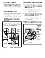
17

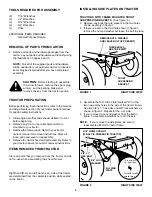
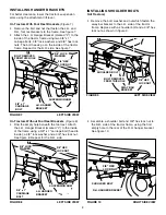
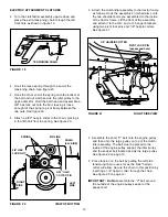
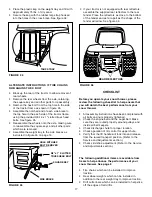
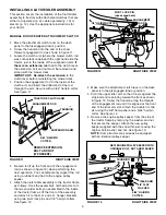
Place the plastic keg on the weight tray and fill with
approximately 75 lbs. of dry sand.

Secure the keg with the rubber tarp strap hooked
into the holes in the cross brace. See figure 34.

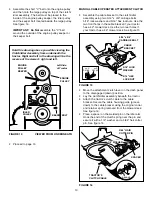
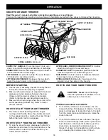
FIGURE  35

CHECKLIST

Before you operate your snow thrower, please
review the following checklist to help ensure that
you will obtain the best performance from your
snow thrower.

All assembly instructions have been completed with
all bolts and nuts properly tightened.

Check the engine belt and the auger belt. Make
sure they are routed properly around pulleys and
inside all belt keepers.

Check discharge chute for proper rotation.

Check operation of tilt control for upper chute.

Verify that the lift handle will lock into and release
from the raised transport position. (Refer to the
Service and Adjustments section.)

Check skid shoe adjustment. (Refer to the Service
and Adjustments section.)

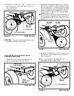
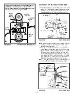
3/8" x 1" SLOTTED
TRUSS HEAD BOLT

SQUARE KEY

SIDE BRACE

HOLE WITH HEX
BOLT REMOVED

The following additional items are available from
Sears to help enhance the performance of your
snow thrower. See page 2.

Tire chains which can be installed to improve
traction.

Rear wheel weights which can be installed in
addition to the rear weight tray to improve traction.

Drift cutter bars which can be installed to help slice
off the edges of tall drifts.

FIGURE  34

ALTERNATE INSTRUCTIONS IF TIRE CHAINS
RUB AGAINST HEX BOLT

Block up the rear of the tractor to allow removal of
rear wheels.

Remove the rear wheels from the axle, retaining
the square key and all other parts for reassembly.

Remove the hex bolt from the top hole in the side
of the tractor frame as shown in figure 35.

Assemble the notched end of each side brace to
the top hole in the each side of the tractor frame,
using the provided 3/8-16 x 1" slotted truss head
bolts. See figure 35.

Reassemble the wheels onto the axle, making sure
to reassemble the square keys and all other parts
which were removed.

Assemble the weight tray to the side braces as
instructed in figure 33 on page 16.

TARP STRAP

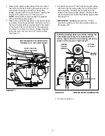
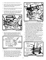
REAR REFLECTORS

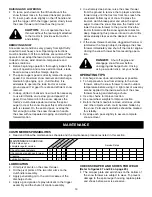
If your tractor is not equipped with rear reflectors,
assemble the supplied rear reflectors to the rear
fender. Place the reflectors as close to the bottom
of the fender and as far apart as the shape of the
fender will allow. See figure 36.

FIGURE  36

Содержание 486.248392

Страница 1: ...m craftsman CAUTION Before using this product read this manual and follow all Safety Rules and Operating Instructions Safety Assembly Operation Maintenance Parts IMPORTANT READ THIS FIRST For Missing Parts or Assembly Questions Please Call 866 576 8388 Mon Fri 7 am 5 pm CST FAX 217 728 2032 or e mail info agri fab com Missing parts will be sent UPS in 24 hours directly to your home ...

Страница 2: ...pair any defect in material or workmanship free of charge If this snow thrower is used for commercial or rental purposes this warranty applies for only 90 days from the date of purchase This warranty does not cover repairs necessary because of operator negligence or abuse including the failure to maintain the equipment according to instructions contained in the owner s manual WARRANTY SERVICE IS A...

Страница 3: ...starts to vibrate abnormally stop the engine immediately and check for the cause Vibration is generally a warning of trouble Stop the engine whenever you leave the operating position before unclogging the snow thrower or making any adjustments or inspections Take all possible precautions when leaving the unit unattended Disengage the attachment clutch lever or switch lower the snow thrower shift i...

Страница 4: ...Hex Bolt 1 2 x 1 1 4 B 4 Hex Bolt 3 8 x 1 Thread Forming C 2 Hex Bolt 5 16 x 1 3 4 D 6 Hex Bolt 1 4 x 1 E 2 Slotted Truss Head Bolt 3 8 x 1 F 4 Carriage Bolt 3 8 x 1 G 2 Carriage Bolt 5 16 x 1 3 4 H 2 Carriage Bolt 5 16 x 1 1 4 I 6 Carriage Bolt 5 16 x 1 J 2 Carriage Bolt 5 16 x 3 4 K 4 Shoulder Bolt 3 8 x 5 8 L 1 Lock Washer 1 2 M 10 Lock Washer 3 8 N 14 Lock Washer 5 16 O 2 Bowed Washer P 7 Wash...

Страница 5: ... Not used on some models 8 Chute Crank Rod Assembly 9 Support Tube Crank Rod 10 Lift Handle Tube and Cable 11 Cable Bracket 12 Plastic Keg 13 Left Hand Hanger Bracket Stamped L 14 Right Hand Hanger Bracket Stamped R 15 Clutch Idler Assembly 16 V Belt Drive 17 V Belt Auger Attached to Housing Assembly 18 Chute and Control Cable Assembly 19 Housing Assembly 20 Weight Tray Hardware Package Stored ins...

Страница 6: ...r and do not re use while assembling the snow thrower CAUTION Before starting to assemble the snow thrower remove the spark plug wire s set the parking brake and remove the key from the tractor ignition INSTALLING SIDE PLATES ON TRACTOR FIGURE 2 RIGHT SIDE VIEW TRACTORS WITH FRAME MOUNTED FRONT SUSPENSION BRACKETS See figure 1 Remove any bolts that are present in the two holes shown as empty in fi...

Страница 7: ...r 16 front tires This end for all smaller tires IMPORTANT If you remove the side plates be sure to reassemble all bolts to tractor frame Attach the R H Side Plate marked R to the right side of the tractor frame as shown in figure 5 For the front hole use a 3 8 x 1 hex bolt a 3 8 lock washer and a 1 2 flat washer Use the flat washer as a shim between the frame and the side plate For the rear hole u...

Страница 8: ... marked L to the inside of the frame using a 3 8 x 1 carriage bolt head to inside a 3 8 lock washer and a 3 8 hex lock nut See figure 8 Repeat for the R H side Assemble a shoulder bolt and 3 8 hex lock nut to the R H side of the tractor frame using the first empty hole to the rear of the R H hanger bracket See figure 10 FIGURE 9 LEFT SIDE VIEW INSTALLING SHOULDER BOLTS All Tractors Remove the bolt...

Страница 9: ...r Attach the clutch idler assembly to the tractor frame as follows Hook the assembly s notched arms onto the two shoulder bolts you assembled to the inside of the tractor frame Lift the front of the assembly and attach it to the R H and L H hanger brackets using two pivot lock pins and 1 8 hairpin cotters See figure 12 FIGURE 12 RIGHT SIDE VIEW FIGURE 11 RIGHT SIDE VIEW ENGAGEMENT ROD 5 64 HAIRPIN...

Страница 10: ...rs and 5 16 hex locknuts Use the two front holes in the cable bracket if your tractor has a 42 mower deck Use the two rear holes if your tractor has a 46 mower deck See figure 15 Move the attachment clutch lever on the dash panel to the disengaged down position Lay the clutch idler assembly beneath the tractor Attach the tractor s clutch cable to the cable bracket Secure the cable housing guide gr...

Страница 11: ...ve the engine pulley keeper from the side of the tractor frame by removing the washer and nut that secure the keeper Attach the new pulley keeper supplied with the snow thrower reusing the original bolt washer and nut See figure 17 NOTE Some tractors may already be equipped with an identical pulley keeper Attach the clutch idler assembly to the tractor frame as follows Hook the assembly s notched ...

Страница 12: ...e bolt leaving it loose enough for the spring to pivot freely between the two nuts See figure 20 Attach a 3 32 hairpin cotter to the chain placing it in the fifth link from the spring See figure 20 FIGURE 19 FIGURE 21 RIGHT SIDE VIEW Assemble the short V belt onto the engine pulley and then onto the large pulley on top of the clutch idler assembly The belt must be placed to the inside of the engin...

Страница 13: ...le in the lift rod Place the threaded fitting into the slot in the lift bracket with one hex nut above and one hex nut and the lock washer below the slot Tighten the nuts adjusting them to eliminate slack in the cable wire See figure 24 Refer also to the Service and Adjustments section on page 20 in this manual HINT For easier assembly of the lift release cable tilt the snow thrower forward onto t...

Страница 14: ...x lock nuts Tighten carefully so that the nuts are snug but do not dig into the plastic chute keepers See figure 28 Place the plastic cap onto the short end of the anti rotation bracket See figure 28 Position the crank rod spiral so that it does not rub against the bottoms of the notches in the chute flange Tighten the nuts See figure 27 Check if the crank rod rotates the chute freely If not loose...

Страница 15: ...R INSTALLING THE AUGER BELT The auger belt comes preassembled to the pulleys on the snow thrower housing Make sure the belt passes over the top of the auger pulley and then twists 1 4 turn to pass underneath each side idler pulley The V side of the belt must mate with the grooves of the pulleys See figure 30 FIGURE 31 VIEWED FROM UNDERNEATH Hold this drawing above you while viewing the Clutch Idle...

Страница 16: ...the side plates From the left side of the tractor install the attachment pin through the holes securing it with the 1 8 hairpin cotter Refer back to figure 29 on page 15 FIGURE 33 SETTING THE AUGER BELT TENSION Pull the tensioning chain until the end of the spring is pulled through the hole in the side of the Clutch Idler assembly Install the 1 8 hairpin cotter through the end of the spring securi...

Страница 17: ...ce of your snow thrower See page 2 Tire chains which can be installed to improve traction Rear wheel weights which can be installed in addition to the rear weight tray to improve traction Drift cutter bars which can be installed to help slice off the edges of tall drifts FIGURE 34 ALTERNATE INSTRUCTIONS IF TIRE CHAINS RUB AGAINST HEX BOLT Block up the rear of the tractor to allow removal of rear w...

Страница 18: ...eared Refer to the Service and Adjustments section Make sure the tractor engine has the correct oil for winter operation SAE 5W 30 Refer to tractor owner s manual HOW TO START YOUR SNOW THROWER The tractor should be sitting with the engine running at full throttle Move the attachment clutch to the engaged position starting the snow thrower before the tractor clutch is engaged HOW TO STOP YOUR SNOW...

Страница 19: ...d For maximum snow removal and discharge maintain high engine r p m full throttle It is advisable to operate the lawn tractor at a slow ground speed 1st gear for safe and efficient snow removal In deep drifted or banked snow it will be necessary to use full throttle and a slow ground speed 1st gear Drive forward into the snow depress the tractor s clutch brake pedal and allow the spiral auger to c...

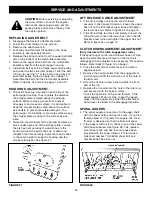
Страница 20: ...ely Adjust both skid shoes to the same height to keep the housing and the scraper plate level See figure 37 LIFT RELEASE CABLE ADJUSTMENT If the lift rod does not lock the snow thrower securely in the transport position loosen the upper hex nut on the lift bracket a few turns and tighten the lower hex nut Refer to figure 24 on page 13 If the lift rod fails to unlock completely to lower the snow th...

Страница 21: ...thrower to the ground Remove the attachment pin See figure 29 on page 15 Lock the snow thrower s lift handle in the down position to decrease belt tension Release the spring tension from the auger belt idler arm on the bottom of the clutch idler assembly Remove the auger drive belt from the clutch idler assembly See figure 31 on page 15 Pull the spiral auger housing assembly off of the tractor CAU...

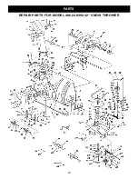
Страница 22: ...22 PARTS REPAIR PARTS FOR MODEL 486 248392 42 SNOW THROWER ...

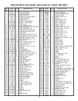
Страница 23: ...ley V Type 5 1 2 51 738 0680 1 Shaft 52 750 0456 1 Spacer 53 750 0660 1 Spacer 54 43003 14 Lock Washer 3 8 55 714 0161 2 Key 56 741 0919 2 Bearing Ball REF PART QTY DESCRIPTION NO NO 57 08253B 1 Housing Bearing 58 15296A 1 Housing Open Bearing 59 14088B 1 Spacer Spindle 60 44377 2 Hex Bolt 3 8 24 x 1 61 736 0247 3 Washer 62 43063 3 Hex Bolt 5 16 18 x 1 63 46989 1 Belt V Type Drive 64 47846 1 Belt ...

Страница 24: ...24 REPAIR PARTS FOR MODEL 486 248392 42 SNOW THROWER ...

Страница 25: ...5 2 Bushing 3 8 Plastic 41 703 2735A 1 Bracket Chute Crank 42 720 0201A 1 Knob Crank REF PART QTY DESCRIPTION NO NO 43 44917 1 Palnut 3 8 45 63579 1 Assembly Chute Crank Rod 46 784 5604 1 Handle Chute Tilt 47 720 0232 1 Knob 48 603 0302 1 Assembly Chute Tilt Bracket 49 731 1313C 1 Guide Cable 50 746 0928 1 Cable Chute Control 51 746 0929 1 Cable Chute Control with Clip 52 43064 5 Nut Hex Lock 5 16...

Страница 26: ...26 NOTES ...
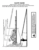
Страница 27: ...ration of your tractor and snow thrower Refer also to the instructions in your vehicle owners manual CAUTION DO NOT OPERATE YOUR TRACTOR AND SNOW THROWER ON A SLOPE IN EXCESS OF 10 DEGREES BE SURE OF YOUR TRACTOR S TOWING AND BRAKING CAPABILITIES BEFORE OPERATING ON A SLOPE AVOID ANY SUDDEN TURNS OR MA NEUVERS WHILE ON A SLOPE ...

Страница 28: ...arts accessories and owner s manuals that you need to do it yourself call Sears PartsDirectSM 1 800 366 PART 6 a m 11 p m CST 1 800 366 7278 7 days a week www sears com partsdirect To purchase or inquire about a Sears Service Agreement 1 800 827 6655 7 a m 5 p m CST Mon Sat Para pedir servicio de reparación a domicilio y para ordenar piezas con entrega a domicilio 1 888 SU HOGAR SM 1 888 784 6427 ...

Отзывы: