background image

Содержание 486.244071

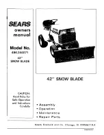
Страница 1: ... Model No 486 244071 42 SNOW BLADE CAUTION Read Rules for Safe Operation and Instructions Carefully 42 SNOW BLADE Assembly Operation Maintenance Repair Parts Sears Roebuck and Co Chicago Ill 60684 U S A PRINTED IN U ...

Страница 2: ...hment 2o Never operate tractor and snow blade without wearing proper clothing suited to weather conditions and operation of controls 3 Never allow children to operate tractor and snow blade and do not allow adults to operate without proper instructions 4 Always begin with transmission in first low gear and engine at Eowspeed and gradually increase speed as required 42 SNOW BLADE CARTON CONTENTS AL...

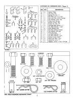
Страница 3: ... K L M N 0 P Q R S T U CARRIAGE 3 8 x 1 318 LOCK WASHER 3 8 NUT Flat Washer 7 16 Std Angle Lock Spring Hairpin Cotter 1 8 Cotter Pin 1 8 x 1 Carriage Bolt 3 8 16 x 1 Hex Bolt 3 8 16 x 1 1 4 Lock Washer 3 8 Hex Nut 3 8 16 Thread Flat Washer 3 8 Std Pivot Bushing Hex Bott 3 8 16 x 1 Hex Bolt 3 8 16 x 3 4 Hairpin Cotter 3 32 Clevis Pin 3 8 x 3 4 Clevis P in 1 2 x 1 Washer 17 32 x 1 1 2 x 10 Ga 3 8 x ...

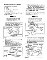
Страница 4: ...SPRING __ L_ G_R S _ BR_CKET_ P VOT _ _ _ in _ _ BRACKET CHANNEI_ _ j x 1 SPRING PIN Using a hammer drive 1 4 x 1 spring pin through slot in bracket and hole in end of lock bars until flush with bracket See figure 3 Tighten 3 8 hex nets left loose in step 1o ASSEMBLY OF SNOW BLADE TO LAWN TRACTOR Remove mower or any other attachment you may have mounted to your tractor Mark all loose parts and sav...

Страница 5: ... PULLEY BOLT 112 HEX NUT CHANNEL ASS Y FIGURE 8 6o FRAME MEMBER Assemble blade assembly to channel assembly by sliding one end of pivot bar into right hand bracket and then sliding back into left hand bracket See figure 9_ Secure by assembling two 1 8 x 1 cotter pins into small holes near ends of pivot bar Spread ends to retain NOTE Blade shoes are factory assembled to blade assembly in ower setti...

Страница 6: ...ough 3 8 flat washer through pivot bushing through large hole in lift arm link near angle end and through hole in long arm nearest the end Secure with one 3 8 lock washer and one 3 8 hex nut See figure 12 NOTE Lift arm link must pivot freely I_ NOTE Lift arm link must be positioned as shown in figures 12 and 13 Assemble one 3 8 x 3 4 hex bolt from inside through second hole from end of long arm Se...

Страница 7: ...e with one 1 8 hair pin cotter on inside 17_ Assemble guide bracket assembly shaft end into the teft hand hitch plate See figure 16 Slide guide assembly back to the right and into hole of the right hand hitch plate Secure with a 1 8 large hairpin cotter ih each end See figure 17 Lower front end of guide bracket assembly to straddle channel assembly FRONT PIVOT SHAFT L HITCH PLATE R H GUIDE BRACKET...

Страница 8: ...lade to transport position pull back on angle lock bars to release the blade and pivot to the right center or left positions_ Release lock bars to lock To adjust blade angle from the tractor seat Raise blade to transport position shift tractor to low speed range pull back on rope to release angle lock bars Move tractor forward slowly dragging the right or left end of blade against snow bank or oth...

Страница 9: ... 17132 x 1 1 2 FI WASH LIFT 1 8 HAIRPIN COTTER ASS Y FIGURE 19 9 Refer to figure 20 below and remove 1 8 large hairpin cotters from ends of guide bracket assembly and remove guide bracket assembly ___ r_ _Jr L H HITCH PLATE GUIDE BRACKET ASS Y FIGURE 20 4_ o Refer to figure 20 above and remove 1 8 large hairpin cotters from ends of channel assembly pivot shaft and remove keeper plates Lift the cha...

Страница 10: ...ILl J 0 Z CCJ wll sit _q i 0 _ O0 J a 0 0 I L q r_ I11 10 ...

Страница 11: ...l a J Z cn I w r_ o _f m O0 _J w 0 0 U R a I W J 9 o _ _ C_x_ _ _ x x_ x x _ _ _o o _ _o _ _ _ _c 1 x v 0 _ _ cO _ o_ _ _ _ _ o_ _ _ _ _ __ _ _ _ o ___0___0 __ 1t o o o E E o o D o Z _ m x _x d _ 0_o m _D ...

Отзывы: