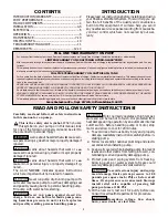
background image

INSTALLATION

5

1. Wrap male pipe threads being attached to pump

with one or two layers of Teflon tape. Cover entire
threaded portion of pipe.

2. Do not overtighten threaded fittings in the plastic

pump. Be sure you do not try to tighten joint past
thread stop in pump port!

3. If leaks occur, remove fittings, clean off old tape,

rewrap with two to three layers of tape and remake
the connection. If joint still leaks, replace the fit-
tings (fittings may be undersized).

4. Be sure to support all piping connected to the

System.

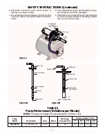
Horizontal Piping from Well to Pump

When the pump is offset more than 25 feet from the
well, horizontal suction pipe size should be increased
to reduce friction losses. Never install a suction pipe
that is smaller than the suction tapping of the pump.

1-1/4”

1-1/2”

2”

Up to 25 Ft.

25 to 50 Ft.

50 to 200 Ft.

Discharge Pipe Sizes

When the pump is some distance from the house or
point of water use, the discharge pipe size should be
increased to reduce pressure losses caused by friction.

1”

1-1/4”

1-1/2”

Up to 25 Ft.

25 to 100 Ft.

100 to 600 Ft.

Tank

Tanks are pre-charged with 30 PSI air pressure at the
factory. Your tank requires an air charge of 30 pounds
per square inch (PSI) for proper operation; check tank
pressure with tire gauge to determine if air charge
needs adjustment. Tank pre-charge should be checked
annually; see instructions at right.

In areas where the temperature is high for long peri-
ods of time, the tank pre-charge pressure may increase.
This may reduce the tank drawdown (amount of water
available per cycle). If this occurs, reduce the pre-
charge pressure to two PSI below the pump cut-in set-
ting of the pressure switch (normally to 28 PSI).
It is necessary to flush all air out of the piping system
and water reservoir portion of the pre-charged tank.
This is required on new installations, pumps requiring
repriming and pumps that have been disassembled for
service. Do this as follows:

1. Open faucets furthest from tank and allow pump to

operate.

2. Air in the system will cause a sputtering flow; allow

faucets to run until you have a steady, air free
stream.

3. Open and close faucets repeatedly until you are

sure all air has been removed.

4. If stream does not become steady, air may be leak-

ing into the system; check for leaks in the piping on
the suction side of the pump.

NOTICE:

To prevent waterlogging, check tank air

charge annually.

To Check Tank Air Charge

If drawdown (amount of water available per cycle) de-
creases significantly, check as follows:

1. To check air charge in tank, shut off electric power

to pump, open faucet near tank, and drain com-
pletely.

2. At the air valve in top of tank, check air pressure

with standard tire gauge. Air pressure should be
same as pump pressure switch cut-in setting (30
PSI).

3. If the air pressure is below the cut-in setting, add air

to the tank. Use an air compressor or a portable air
storage tank.

4. Use soap or liquid detergent to check for air leaks

around air valve. Continuous bubbling indicates a
leak. If necessary, install new core in air valve. This
is the same as those used for automobile tubeless
tires.

H

2

0

H

2

0

H

2

0

612 1293

1

2

3

4

5

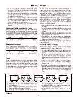
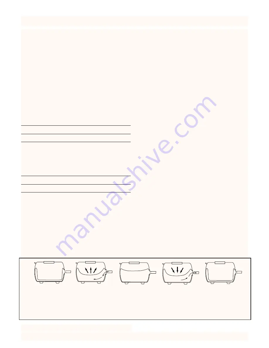
1. Tank nearly empty – air expands filling area above

vinyl separator.

2. Water begins to enter tank – air is compressed

above separator as it fills with water.

3. Pump-up cycle completed – air now compressed

to cut off setting of pressure switch.

4. Water being drawn from tank – compressed tank

air forces water out of separator.

5. Separator completely empty – new cycle ready to

begin.

Figure 3

Water

Water

Water

Содержание 390.252156

Страница 1: ...se of This Product Save This Manual For Future Reference Sears Roebuck and Co Hoffman Estates IL 60179 U S A Safety Instructions Installation Electrical Maintenance Repair Parts PRINTED IN U S A CRAFTSMAN 1 2 HP SHALLOW WELL WATER SYSTEM Form No F642 9708 Rev 8 4 97 FOR POSITION ONLY Photo may vary from actual product ...

Страница 2: ...to well con taminating well and possibly damaging pump 4 Protect pump and piping system from freezing Allowing pump or water system to freeze could severely damage pump and voids warranty To avoid serious injury and equip ment damage limit system pressure to 100 pounds per square inch PSI or below at all times Over pressure can cause tank blowup install relief valve capable of passing full pump vo...

Страница 3: ...f 20 feet or less Plastic Pipe Plastic Pipe Foot Valve and Strainer Coupling Well Seal Dug or Cased Well 611 1293 Figure 1 Figure 2A Figure 2B Check Valve Steel Drive Pipe Drive coupling Driven point 6 Disconnect electrical power source before in stalling or working on pump 7 Ground pump with a ground wire run from ground ing lug on motor to a grounded lead in the service panel 8 Line voltage and ...

Страница 4: ...It should be in stalled five to ten feet below the lowest level to which the water will drop while the pump is operating pumping water level To keep sediment from clog ging the strainer be sure it is five to ten feet above the bottom of the well Before installing the foot valve make sure that it works freely When using a foot valve a priming tee and plug as shown in Figure 1A Page 3 are recommende...

Страница 5: ...mally to 28 PSI It is necessary to flush all air out of the piping system and water reservoir portion of the pre charged tank This is required on new installations pumps requiring repriming and pumps that have been disassembled for service Do this as follows 1 Open faucets furthest from tank and allow pump to operate 2 Air in the system will cause a sputtering flow allow faucets to run until you h...

Страница 6: ... on power to pump ELECTRICAL OPERATION Priming the Pump NOTICE To properly prime the pump install a pipe tee in the discharge piping see Figure 1A Page 3 To prevent damage to internal parts do not start motor until pump has been filled with water To prime pump 1 Remove priming plug Purchase separately Figure 1A Page 3 2 Fill pump with water 3 Replace priming plug using Teflon tape or Plasto Joint ...

Страница 7: ...piping from tank and pump To avoid serious or fatal injury be sure all air pressure has been released from tank before proceeding to step 5 5 Remove nuts and washers from tank inlet flange Key No 2 Page 14 Tap inlet flange to break seal Remove flange 6 Wherever convenient hold bag with pliers and cut with single edge razor blade or sharp knife Bag will not come out in one piece Continue pulling an...

Страница 8: ... be needed the pump and piping do not need to be dis connected or disturbed 1 Disassemble pump as follows A Disconnect power B Drain pump by opening drain cock Remove pressure switch tubing from fitting on top of pump To avoid serious injury release all pressure from system before attempting to re move clamp from pump C Remove clamp Key No 10 Page 12 D Remove pump base mounting bolts Motor as semb...

Страница 9: ...until rubber drive ring hits shaft shoulder NOTICE BE SURE you do not chip or scratch seal face on shaft shoulder or seal will leak I Screw impeller on shaft clockwise while hold ing shaft with 7 16 open end wrench on shaft flats This will automatically locate seal in place See Figure 8 J Remount diffuser on seal plate Cleaning Impeller 1 Follow steps 1A through 1E under Disassembly and Assembly o...

Страница 10: ... allowed to escape before the water is used This can be done as shown in Figure 9 A good way of delivering gas free water is to suspend a pipe closed at the bottom and open at the top sur rounding the suction pipe Since the gases rise in the well casing the water sucked down through the pipe and into the suction pipe is free of gas This type of well must be vented to the outside of any enclosure N...

Страница 11: ...d causing excess friction new steel pipe above 3 Offset piping is too small in size 3 Use larger offset piping Pump pumps water 1 Pressure switch is out of adjustment 1 Adjust or replace pressure switch but does not shut off or contacts are frozen 2 Faucets have been left open 2 Close faucets 3 Jet or impeller is clogged 3 Clean jet or impeller 4 Motor is wired incorrectly 4 Refer to instructions ...

Страница 12: ... 27 28 29 30 587 1193 24 SEARS 1 2 HP SHALLOW WELL WATER SYSTEM Pump Only Model 390 252156 To Order Parts in the U S A Call Sears Product Service 1 800 366 7278 To Order Parts outside the U S A Call Your local Sears Service Center or Store 1A L1 L2 1B 1C 1D 1E Wiring omitted for clarity ...

Страница 13: ...ozzle 14 N76 29P Insert 15 J20 18 Gasket 16 N176 28PB Tank Body Assembly Front Half Includes Key No s 11 12 13 14 15 16 19 20 21 23 and 24 16 N76 28P Tank Body Only Front Half 17 U37 673P Switch Tube 18 U111 212T 90 Hose Barb 19 U9 226 O Ring Check Valve 2 1 4 x 2 x 1 8 20 N166 5P Check Valve 21 WC78 41T Pipe Plug 1 8 NPT 2 Required 22 U212 68T Draincock 1 4 NPT 23 U30 742SS Screw 10 16 x 1 1 8 4 ...

Страница 14: ... Store Model 390 252156 Key 1 2 HP Qty No Part Number Used Description 1 29135 1 Tank Assembly Includes Diaphragm Elbow Valve Nuts Washers Inlet Flange U20 13 1 Bag Vinyl U212 160 1 Air Valve w Cap 2 U31 350P 1 Inlet Flange 3 U36 202BT 6 Nut 5 16 18 Hex 4 U78 769P 1 Elbow 1 NPT x 1 Insert 5 U19 55SS 2 Clamp 6 U74 37V 1 Hose 1 x 24 1 2 7 U78 777P 1 Adapter 1 Pipe to 1 NPT REPAIR PARTS Not illustrat...

Страница 15: ...15 ...

Страница 16: ... about an existing Agreement call 9 am 5 pm Monday Saturday 1 800 827 6655 M A I N T E N A N C E A G R E E M E N T America s Repair Specialists REPAIRSERVICES America s Repair Specialists REPAIRSERVICES America s Repair Specialists REPAIRSERVICES Sears Roebuck and Co Hoffman Estates IL 60179 U S A OWNER S MANUAL Model No 390 252156 The model number of your Shallow Well Water System will be found o...

Отзывы: