background image

OPERATOR’S MANUAL

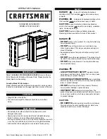
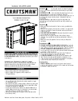
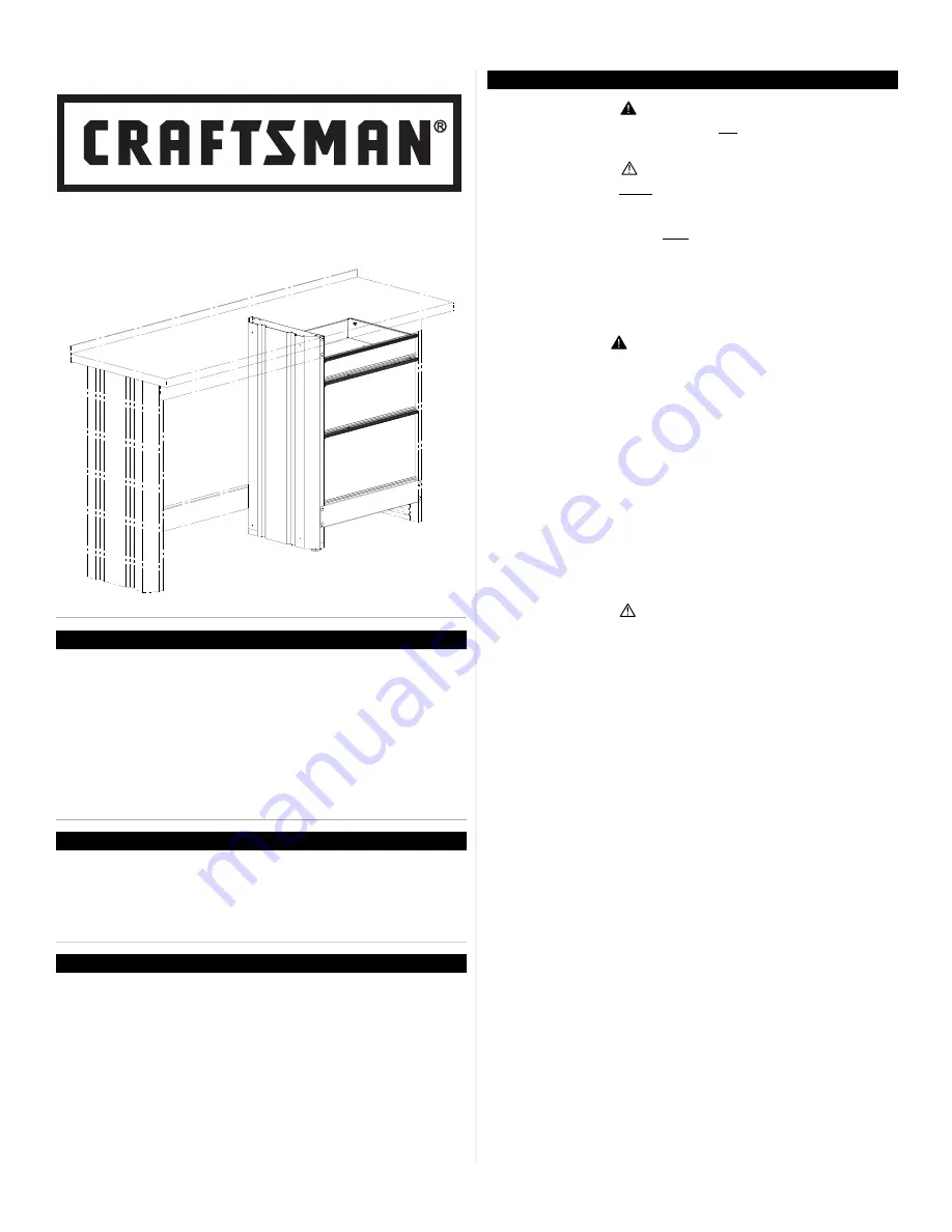
3-DRAwER AccESSORy

MODEL # 14926 & 14927

capacities

Locating Model # information

Model numbers and other information required for service parts is 

located on a white label on the upper right hand corner of the unit.

Maintenance

• weight of the unit is 63 lbs.
• The maximum weight for Drawer should be no more than  

35 lbs.

•  Periodically the surfaces should be cleaned with a mild 

detergent and water.

•  Grease and oil can be removed with most standard cleaning 

fluids. For safety, use a nonflammable cleaning fluid.

•  Auto wax will preserve the unit’s luster finish. Apply the wax as to 

a car. The wax will also help protect the unit against scratches.

•  Lubricate the slides with grease or equivalent, (twice yearly).

F1872

service parts

safety

  DanGer


is used to indicate a hazardous 

situation which, if not avoided, will result in serious injury 

or death.

  WarninG 

indicates a hazardous situation which,

if not avoided, could result in serious injury or death.

  caution

 is used to indicate a hazardous situation 

which, if not avoided, may result in minor injury, moderate 

injury, or property damage.


caution:

 Read and follow all Safety Rules and 

Operating Instructions before first use of this product.


DanGer

  •  

Do not

 stand on this product. you may fall which may   

  cause personal injury.

    •  

Do not 

mount this product on a truck bed or any  


    other moving object. This may cause personal injury or    

    product Damage.

    •  Appropriately secure this product before moving it with  

    a forklift.

    •  

Do not 

tow with power equipment. The product could   

    tip, which may cause personal injury or product damage.

    •   

Do not

 step in the drawers. you may fall which may 

cause personal injury.

 
  WarninG
 

•  

use appropriate safety

 equipment when    

  using power and hand tools. Failure to do so may cause    

  personal injury or product damage.

    •  

use aDequate ManpoWer

 when assembling   

    and moving this unit. Failure to do so may cause personal  

    injury or product damage. 

    •  

Do not

 alter this product in any manner. This may  


    cause product damage or personal injury.

    •  

unit Must Be

 located on a level surface. The  


    product may become unstable and tip if stored or moved    

    on an un-level surface, which may cause personal injury  

    or product damage.


  caution
 

•   

Be carefuL

 when opening more than one drawer.  

The product may become unstable and tip, which may  

cause personal injury or product damage. 

Sears Brands Management corporation, Hoffman Estates, IL 60179  USA

caLL 1-800-366-7278 for service parts. 

Refer to Service 

Parts Drawing for full listing of Service Parts. Please provide the 

Model Number when calling.

Содержание 14926

Страница 1: ... before first use of this product DANGER DO NOT stand on this product You may fall which may cause personal injury DO NOT mount this product on a truck bed or any other moving object This may cause personal injury or product Damage Appropriately secure this product before moving it with a forklift DO NOT tow with power equipment The product could tip which may cause personal injury or product dama...

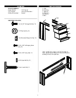
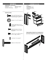
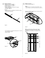
Страница 2: ...y 12 A Side B Front Rail C Drawer 4 D Drawer 9 E Drawer 12 F Slide 8 32 x 3 8 Self tapping Screw Qty 12 When installing this product on an 8 foot workbench frame please remove stiffeners D from rails B prior to installing the kit to the workbench B D TOOLS REQUIRED Socket Wrench 7 16 Socket 11 32 Wrench Cross tip Screwdriver Flathead Screwdriver Square HARDWARE INCLUDED hardware ...

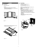
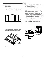
Страница 3: ... Needed Front Rail Qty 1 1 4 20 x 5 8 Carriage Bolt Qty 10 5 16 Washer Qty 10 1 4 20 Serrated Flange Nut Qty 10 NOTE When installing on 8 workbench remove inner support rails before installing side Process NOTE Drawer kit may be installed on left or right side Installation shown on right side Install Side using 6 1 4 20 x 5 8 Carriage Bolt 6 5 16 Washer 6 1 4 20 Serrated Flange Nut Attach Front Ra...

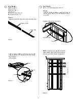
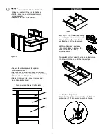
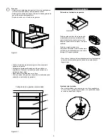
Страница 4: ... may be organized in several configurations below is the slide positioning for the recommended drawer configuration Workbench Slide Screw Figure 3 Figure 3 1 Figure 4 1 F R O N T Attach 2 Drawer Slides to each drawer C D and E using 20 8 32 x 3 8 Screws and 20 8 32 Keps Nuts as shown Wrench tighten 4 Process Separate slide parts See drawer removal instructions Items Needed Drawer 4 Qty 1 Drawer 9 ...

Страница 5: ...Depress the release tabs on both sides this allows the slides to ride over the stops Pull out to remove To reinstall carefully align the slides and slowly push the drawer into the unit until the drawer stops Leveling Foot Adjustment Adjust leveling foot to desired position with flat head screwdriver or 7 16 open end wrench as shown Release Square the unit and adjust for optimum drawer performance ...

Страница 6: ......

Страница 7: ... de usar este producto por primera vez PELIGRO NO se pare sobre este producto Puede caerse y posiblemente lesionarse NO arme este producto en la caja de un camión ni en ningún otro objeto en movimiento Pueden producirse lesiones personales o daños al producto ASEGURE ADECUADAMENTE este producto antes de moverlo con un elevador de horquilla NO remolque con equipos eléctricos Este producto puede inc...

Страница 8: ... y 20 roscas por pulgada cantidad 10 Nivelador de tornillos cantidad 2 Tuerca Keps n º 8 32 cantidad 12 A Lado B Riel delantero C Gaveta de 10 2 cm 4 D Gaveta de 22 9 cm 9 E Gaveta de 30 5 cm 12 F Deslizador Contenido de la caja A Cuando instales este producto en un armazón de banco de trabajo de 8 pies por favor retira el refuerzos D del riels B antes de instalar el kit en el banco mencionado B D...

Страница 9: ...tes de colocar uno de los lados Proceso Nota el kit de gavetas puede instalarse en el lado izquierdo o derecho En la figura se muestra la instalación del lado derecho Instale el lado con 6 Riel 6 Perno con cabeza de hongo de 1 6 cm 5 8 de largo 6 4 mm 1 4 de diámetro y 20 roscas por pulgada Arandela de 7 9 mm y 6 Tuerca de la brida dentada de 6 4 mm 1 4 de diámetro y 20 roscas por pulgada Fije el ...

Страница 10: ...e los deslizadores recomendada para la configuración de las gavetas Gu Figura 3 Figura 3 1 Figura 4 1 P A R T E D E L A N T E R A Fije 2 deslizadores de gaveta Gd a cada gaveta C D y E tal como se muestra en la figura Ajuste con la llave Tornillo Tornillo Tuerca Keps 4 Proceso Separe las piezas de los deslizadores Consulte las instruccio nes de extracción de gavetas Elementos necesarios Gaveta C d...

Страница 11: ... a ambos lados esto permite que los deslizadores corran sobre los topes Tire para quitarlos Para volver a instalar alinee cuidadosamente los deslizadores y presione lentamente la gaveta dentro de la unidad hasta llegar al tope Ajuste del pie nivelador Con el destornillador de punta plana o una llave española de 11 1 mm 7 16 ajuste el pie nivelador a la posición deseada tal como se muestra en la fi...

Страница 12: ......

Отзывы: