background image

Содержание 137.212520

Страница 1: ...anual and follow all its Safety Rules and Operating Instructions Customer Help Line For Technical Support 1 800 843 1682 Safety Instructions Installation Operation Maintenance Parts List Sears Parts Repair Center 1 800 488 1222 Sears Roebuck and Co Hoffman Estates IL 60179 USA Visit our Craftsman website www sears com craftsman Part No 137212520001 ...

Страница 2: ... these chemicals are Lead from lead based paints Crystalline silica from bricks cement and other masonry products Arsenic and chromium from chemically treated lumber Your risk from these exposures varies depending on how often you do this type of work To reduce your exposure to these chemicals work in a well ventilated area and work with approved safety equipment such as dust masks that are specia...

Страница 3: ... for which it was designed 9 USE THE RIGHT TOOL Do not force the tool or an attachment to do a job for which it was not designed 10 USE PROPER EXTENSION CORDS Make sure your extension cord is in good condition When using an extension cord be sure to use one heavy enough to carry the current your product will draw An undersized cord will result in a drop in line voltage and in loss of power which w...

Страница 4: ...ing the workpiece before the switch is turned ON 1 IMPORTANT After completing the cut release the trigger and wait for the blade to stop before returning the saw to the raised position 20 MAKE SURE the blade has come to a complete stop before removing or securing the workpiece changing the workpiece angle or changing the angle of the blade 21 NEVER cut metals or masonry products with this tool Thi...

Страница 5: ...kers may trip frequently if a MOTOR is overloaded overloading can occur if you feed too rapidly or make too many start stops in a short time b LINE VOLTAGE is more than 10 above or below the nameplate voltage rating For heavy loads the voltage at motor terminals must equal the voltage specified on the nameplate c IMPROPER or dull saw blades are used 5 Most motor troubles may be traced to loose or ...

Страница 6: ...wer tool IAWARNING To avoid the risk of personal injury do not modify this power tool or use accessories not recommended by Sears WARNING I Read warnings and conditions on your CARBIDE TIPPED SAW BLADE Do not operate the saw without the proper saw blade guard in place Carbide is a very hard but brittle material Care should be taken while mounting using and storing carbide tipped blades to prevent ...

Страница 7: ... packing material Check each one with the illustration to make certain all items are accounted for before discarding any packing material WARNING I If any part is missing or damaged do not attempt to assemble the miter saw or plug in the power cord until the missing or damaged part is correctly replaced To avoid electric shock use only identical replacement parts when servicing double insulated to...

Страница 8: ... Right Extension Table Stop Plate Positive Stop Locking Lever Quick Cam Miter Table Lock Stand Safety Lock Off Button Laser Guide Locking Lever Cover Plate Upper Blade Guard _ Laser Guide Tab Dust Bag Left Extension Table Stop Plate Table Table Insert iJ _Extension Table Lock Knob J Mounting Hole Base Miter Lock Handle Miter Scale Positive Miter Detents 8 ...

Страница 9: ...aw to a right or left cutting position MITER SCALE Measures the miter angle 0 to 45 left and right MOUNTING HOLES To mount the miter saw to a stable su trace ON OFF TRIGGER SWITCH To start the tool push the safety lock off button and squeeze the trigger Release the trigger to turn off the miter saw POSITIVE STOP LOCKING LEVER Locks the miter saw at a preset positive stop for the desired miter angl...

Страница 10: ...exactly the same manner 6 Join the front and rear frame assemblies using two short upper supports 6 and two short bottom supports 8 carriage bolts and nuts 7 Place all four foot pads 7 onto each leg 8 Place the stand on a level surface and adjust it so all legs are contacting the floor and are at similar angles to the floor Tighten all bolts NOTE Stand should not rock after all bolts are tightened...

Страница 11: ... never carry the miter saw by the switch handle the cutting arm or the miter table handle INSTALLING THE DUST COLLECTION ELBOW AND THE DUST BAG FIG E 1 Install the larger end of the elbow 1 onto the exhaust port 2 NOTE The elbow can be used to attach either the dust bag or a vacuum hose to remove sawdust from the work area Fig E 1__L_ _ INSTALLING THE DUST BAG FIG E l 1 Squeeze the metal collar wi...

Страница 12: ...rclockwise Fig H IMPORTANT Make sure the flats of the blade collars are engaged with the flats on the arbor shaft 3 Place the blade wrench on the arbor bolt 4 Press the arbor lock 5 holding it in firmly while turning the blade wrench counterclockwise When it engages continue to press the arbor lock in while tightening the arbor bolt securely Fig G 5 Rotate the cover plate 3 back until the slot in ...

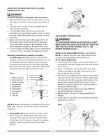
Страница 13: ...JUSTMENT INSTRUCTIONS I AWARNING I TO AVOID INJURY FROM AN ACCIDENTAL START MAKE SURE THE SWITCH IS IN THE OFF POSITION AND THE PLUG IS NOT CONNECTED TO THE POWER SOURCE OUTLET BEVEL STOP ADJUSTMENTS FIG L M N O P NOTE To ensure accurate cuts alignment should be checked and adjustments made prior to use 90 0 Bevel Adjustment 1 Loosen bevel lock handle 1 and tilt the cutting arm completely to the r...

Страница 14: ...ting fast adjustments to the desired position Follow the process below for quickest and most accurate adjustments 1 Lift up on the miter quick lock 1 to unlock the table 2 Move the turntable while lifting up on the positive stop locking lever 4 to align the indicator 2 to the desired degree measurement 3 Lock the table into position by pressing down on the miter quick lock 1 Fig O 3 MITER SCALE IN...

Страница 15: ... the miter handle and move the miter table left or right to the desired angle 3 Release the positive stop locking lever 4 Press down on the Miter Quick Cam locking lever 1 until it locks the miter table in place NOTE The miter Quick Cam locking lever should lock the table and prevent it from moving If adjustment is needed see next step QUICK CAM MITER TABLE LOCK ADJUSTMENT FIG Q 1 Press down and l...

Страница 16: ...to the left 2 Slide out the laser guide assembly by pulling on the tab 4 3 Lock the laser guide assembly into place by pushing the locking lever to the right side of the saw 4 To turn the laser ON or OFF press the rocker switch 5 Fig T B Check Laser Beam Alignment 1 Mark a straight line across a board to serve as a pattern line to test laser alignment Lay the board on the miter table 2 Turn on the...

Страница 17: ...ing screw 3 Fig T 1 NOTE Do not overturn this screw or it may damage internal wiring Maximum screw turn is 1 8 turn in each direction 2 Move laser close to pattern line by turning screw 4 3 Fine tune alignment of laser is achieved by adjusting screw 4 no more than 1 8 turn in each direction Fig T 3 Laser Line Laser Line Pattern Line ...

Страница 18: ...issing bent damaged or broken in any way or any electrical parts don t work turn the saw off and unplug it Replace bent damaged missing or defective parts before using the saw again Maintain tools with care Keep the miter saw clean for best and safest performance Follow instructions for lubricating Don t put lubricants on the blade while it s spinning Remove adjusting wrench from the tool before t...

Страница 19: ... there is no debris between the workpiece and the table or fence Make sure there are no gaps between the workpiece fence and table that will let the workpiece shift after it is cut Keep the cut off piece free to move sideways after it is cut off Otherwise it could get wedged against the blade and thrown violently Only the workpiece should be on the saws table Secure work Use clamps or a vise to he...

Страница 20: ...ore the trigger switch 2 can be activated and the miter saw started I A WARNING Make the switch child proof Insert a padlock or chain with padlock through the hole of the trigger switch and lock it This will preventing children and other unauthorized users from turning the machine on Fig X Finishing a cut Hold the cutting arm in the down position Release trigger switch and wait for all moving part...

Страница 21: ...t common angles for cutting operation To make a miter cut 1 Unlock the miter table by lifting up on the miter quick cam table lock 2 2 While raising the positive stop locking lever up 3 grasp the miter handle 4 and rotate the miter table left or right to the desired angle 3 Release the positive stop locking lever and set the miter at the desired angle making sure the lever 21 4 5 snaps into place ...

Страница 22: ...kpiece check to make sure it is not bowed If it is bowed the workpiece must be positioned and cut as illustrated Do not position the workpiece incorrectly or try to cut the workpiece without the support of the fence This will cause the blade to bind and could result in personal injury Fig DD oo AUXILARY WOOD FENCE FIG FF When making multiple or repetitive cuts that result in cut off pieces of one ...

Страница 23: ...n that fits flat against the ceiling of 52 and a bottom rear angle the section that fits flat against the wall of 38 In order to accurately cut crown molding for a 90 inside or outside corner lay the molding with its broad back surface flat on the saw table When setting the bevel and miter angles for compound miters remember that the settings are interdependent changing one changes the other as we...

Страница 24: ...al injury 1 Flip laser guide locking lever to left 2 Use laser guide tab to pull out laser guide 3 Lift open the battery guide cover 1 4 Install two batteries with 1 5 volt AAA size NOTE When replacing the batteries the battery guide should be thoroughly cleaned Use a soft paintbrush or similar device to remove any sawdust and debris Fig JJ 24 ...

Страница 25: ...er blade guard The lower blade guard is attached to the saw for your protection Should the lower guard become damaged do not use the saw until the damaged guard has been replaced Develop a regular check to make sure the lower guard is working properly Clean the lower guard of any dust or buildup with a damp cloth CAUTION Do not use solvents on the guard They could make the plastic cloudy and britt...

Страница 26: ...INTENANCE section switch released 2 Other See Sears Service Center TROUBLESHOOTING GUIDE SAW OPERATION PROBLEM PROBLEM CAUSE SUGGESTED CORRECTIVE ACTION Blade hits table Misalignment 1 See ADJUSTMENT Cutting Arm Travel section Angle of cut not Miter table unlocked 1 See OPERATION Miter Angle Adjustment accurate Can not 2 Sawdust under table section adjust miter 2 Vacuum or blow out dust WEAR EYE P...

Страница 27: ...08 12 0K7K CR RE ROUND WASHER HD SCREW M61 0 12 0K7Z CR RE TRUSS HD ROUND NECK SCREW M61 0 14 0KA6 CR RE PAN HD TAPPING SCREW M512 10 0KAD CR RE PAN HD TAPPING SCREW M40 7 8 0KB7 CR RE PAN HD TAPPING SCREW M4XI 8 16 0KB8 CR RE PAN HD TAPPING SCREW M4XI8 20 0KB9 CR RE PAN HD TAPPING SCREW MBXI _ l 0 0KBC CR RE PAN HD TAPPING SCREW M516 25 0KBM CR RE PAN HD TAPPING SCREW M418 28 0KD5 CR RE PAN HD SC...

Страница 28: ...R SAW SCHEMATIC FOR SAW MODEL NO 137 212520 OKBC4 084_ 084M b_ OJET 083Y 085X 083v 2ED8 OJUK OKQW 28N2 _2794 29TP _0841 OJZF2 OKR3 290M _ _ f _ 0836 2145 OD 7 ODT4 OJFB OJEM 2E3X 21EF OK7Z OJMM OD7Z OKRI 0KD5_ 2EIG _DS2 W ...

Страница 29: ...D WIRE ASS Y RED 0PLT BEARING COVER 0Q9K FLOW GUIDE 0QGR COMPRESSION SPRING 0QME BRACKET STOP 0QMK RUBBERCAP 0QMR ARMATURE ASS Y 0QMY PROTECTOR WIRE 0QMZ MOTOR HOUSING 0QQS BRUSH HOLDER ASS Y 0QQT BRUSHASS Y 0QR0 BRUSH COVER 0QR2 BEARING BUSHING 0QYW FIELD ASS Y 110A CR RE PAN HD TAPPING SCREW WASHER 110C ARBOR SHAFT ASS Y 2DVD ARM Size cp4 36 6201Z LU 6200ZZ M5 0 8 6 M5 0 8 12 M5 6 35 M5 0 8 6 M5...

Страница 30: ... SCREW 0KRR SERRATED TOOTHED HEXAGON FLANGE NUT 0STZ TRADE MARK LABEL 2A10 CAP HD S NECK BOLT 2E19 BOTTOM SUPPORT BRACKET 2E1A BOTTOM SUPPORT BRACKET 2E1B UPPERSUPPORT 2E1C UPPERSUPPORT 2E1D BRACKET Size 8 16 2 5 M8 1 25 35 M8 1 25 T 7 5 M8 0 25 12 QTY 4 4 4 20 1 16 2 2 2 2 4 2A10 6 0KE34 0J4F4 2E1B2 2EIA2 0KRR2o 0STZ 2E1 D4 J 093B4 2E192 2E1C2 ...

Страница 31: ...n equipment and electronics call or go on line for the location of your nearest Sears Parts Repair Center 1 800 488 1222 Call anytime day or night U S A only www sears oom To purchase a protection agreement U S A or maintenance agreement Canada on a product serviced by Sears 1 800 827 6655 U S A 1 800 361 6665 Canada Pars pedir servicio de reparaci6n a domicilio y pars ordenar piezas 1 888 SU HOGA...

Отзывы: