background image

Содержание 113.228000

Страница 1: ...d under belt guard You should record both model and serial number in a safe place for future use CAUTIION Read GENERAL and ADDITIONAL SAFETY iNSTRUCTIONS carefully CRI IFTSMttN_ 12 INCH WOOD TURNING LA THE assembly e operating repair parts Sold by SEARS ROEBUCK AND CO Chicago IL 60684 U S A Part No 70053 Prir_ _ed tr_ Li_ A ...

Страница 2: ...t to do a job for which it was not designed 11 WEAR PROPER APPAREL Do not wear loose clothing gloves neckties or jewelry _rings wristwatches to get caught in moving parts 21 NONSLIP footwear is recommended Wear protective hair covering to contain long hair Roll long sleeves above the elbow 12 USE SAFETY GOGGLES Head Protection 22 Wear safety goggles must comply wilh ANSI Z87 1 at alt times Everyda...

Страница 3: ...ut removing and storing the switch key j Never operate the Lathe with protective cover on the unused shaft end of the motor removed Hang your turning tools on the wall toward the tail stock end of the Lathe Do not lay them on the bench so that you must reach over the revolving workpiece to select them 9 Keep firm hold and control of the turning tool at all times Special caution must be exercised w...

Страница 4: ... FURNISHED ARE DE SIGNED TO RUN THE LATHE AT THE COR RECT SPEEDS WHEN USED WITH A 1725 R P M MOTOR DO NOT USE A 3450 R P M MOTOR TO INCREASE THE SPEED BECAUSE IT COULD BE DANGEROUS WEAR YOUR The operation of anv power tool can result in foreign objects being thrown into the eyes which can result in severe eye damage Always wear safety goggles complying with ANSI Z87 1 shown on Package before comme...

Страница 5: ...quipped with a 3 conductor cord and grounding type plug which has a grounding prong approved by Underwriters Laboratories The ground conductor has a green jacket and is attached to the tool housing at one end and to the ground prong in the attachment plug at the other end This plug requires a mating 3 conductor grounded type outlet asshown If the outlet you are planning to use for this power tool ...

Страница 6: ...unted for before discarding any packing material If any parts are missing do not attempt to assemble the lathe olug in the power cord or turn the switch on until the missing parts are obtained and are installed correctly Using a 7 16 wrench remove the wood blocks attached to the Lathe Save the nuts bolts and washers you wilt need for attaching the Lathe to the bench Remove the protective oil that ...

Страница 7: ... screw to loosen the tocknut inside Turn the foot so it is flat on the bench and tighten the screw 4 Mark the location on the bench of the hole in foot 5 Remove the Lathe and drill a 3 8 hole to attach the foot 6 Position the Lathe and insert the bolts from the top Place a flat washer a Iockwasher and a nut on the bolts and tighten the nuts 7 Position the motor over the mounting holes NOTE When us...

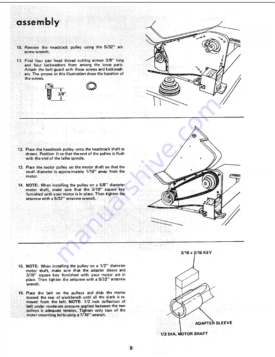
Страница 8: ...away from the motor 14 NmOoToEr shWhf_n _1_s_l _tgrteh_hPa_It_ eO_ 65fS _lud_ra_n_tee furnished with your motor is in place Then tighten the setscrew with a 5 32 setscrew wrench 3 16 x 3 16 KEY 15 NOTE When installing the pulley on a 112 diameter motor shaft make sure that the adapter sleeve and 3 I6 square key furnished with your motor are in place Then tighten the setscrew with a 5 32 setscrew w...

Страница 9: ...ach the belt guard plate to the bench with the two screws Make sure the plate is PARALLEL to the belt 19 Plug motor cord into outlet on back of switch box DO NOT plug motor cord into power source outlet 20 Position the two cords as shown and clamp them to the table with two cable clamps and 1 2 wood screws from the loose parts bag 21 Coil up the slack in the cord and tie it with apiece of tape CLA...

Страница 10: ...p 4 To remove spur center from spindle hold the spindle pulley with one hand and Using a wrench or pair of pliers turn the hex nut counterclockWise until center is ejected 5 To remove cup Center insert a 114 wood dowel or brass rod through the hole in the tailstock ram Hold the center with one hand and tap the dowel or rod with a hammer TAILSTOCK RAM FOOT WARNING DON TCONNECT POWER CORD TO ELECTRI...

Страница 11: ...Lathe unattended until it has come to a complete stop and you have removed the switch key Do not cycle the motor switch on and off rapidly as this may cause the faceplate or sanding disc to loosen In the event this should ever occur stand clear of the face plate or sanding disc until it has come to a complete stop retighten it 11 ...

Страница 12: ...K MOTOR ROTATION ROTATION The Lathe must rotate counterclockwise when viewed from the spindle end NOTE Make sure the spur center is removed from the spindle 1 Plug the Lathe power cord into a properly grounded outlet See page 4 _ 2 Standclearof the Lathespindleandturn the switchON Notice the rotation of the soindle If it is NOT turning COUNTERCLOCKWISE Removethe Lathe power cord plug from the outl...

Страница 13: ...cuts for fluting or feeding or for dividing face plate work DO NOT USE FOR REMOVING FACEPLATES 3 SPINDLE LOCK HOLE For remov ng faceptatesor sanding discs insert a setscrew wrench large nail or bolt in the hole to hold the spindle while unscrewing facepiate or sanding disc 4 TOOL REST BRACKET LOCK Clamps the tool rest bracket to the bed 5 TOOL REST LOCK Clamp the too rest to the tool rest base 6 T...

Страница 14: ...the setscrewir_ the headstock and the screw in the end of the taitstock 3 16 SETSCREW WRENCH HEADSTOCK r 3 16 SETSCR EW TAI LSTOC K FOOT SCREW HANDWHEEL 12 TAILSTOCK supports the workpiece for spindle turning The tailstock contains a brass screw which bears against the key on the underside of the bed This screw pre vents excessive looseness rocking back and forth of the tailstock I Loosen the Iock...

Страница 15: ... the belt with your right hand 3 Continue to rotate the pulley while pushing on the belt until it climbs down into the third step of the motor pulley 4 Now rotatethe spindle pulley CLOCKWISE with your right hand while pushing on the belt with your left hand The belt will cJimb up into the third step of the spindle pulley To make the lathe go faster the belt must be shifted o_t ward 1 Rotate the sp...

Страница 16: ...p center into the wood Use a wooden mallet or a plastic hammer If you don t have one use a steel hammer but put a piece of Wood on the end of the cup center to protect it 6 Remove the cup center and drive the spur center into the other end of the wood Make sure the spurs are in the saw cuts Remove the spur center 7 Make sure the centers and the hole in the spindle and the tailstock ram are clean I...

Страница 17: ... of the toot rest base Lock the tool rest base and the tool rest TOOL R EST 1 8 WOOD Look at the speed chart Notice that a 2 square turning up to 18 tong should run at 875 R P M for roughing Move the V belt on the pulleys to the slowest speed Rotate the wood by hand to make sure that the corners do not strike the toot rest 17 ...

Страница 18: ...ips into the slot This will allow the index pin to engagein one of the holes in the pulley and pre vent the spindle from turning 2 AdjuSt the toot rest approximately at the centerline and make a mark 3 Pull out the index pin and slowly rotate the workpiece until the pin slides into the next hole in the pulley 4 Do this six times and put the next mark on the work piece The _wo marks will be spaced ...

Страница 19: ...ail stock to more more freely If the power cord is worn or cut or damaged in any way have it replaced immediately For motor maintenance follow instructions furnished with motor WIRING DIAGRAM WHITE MOTOR _ r Insulated OUTLET SWI I i_H Cap Flag I POWER _ CORD im m 11I lubrication All of the BALL BEARINGS are packed with grease at the factory They require no further lubrication Periodically lubricat...

Страница 20: ...D unless repair is done by a qualified service technician Repair service is available at your nearest Sears Store t Adjust bert tension see Assembly Section Lathe slows down 1 V belt too loose when turning Tailstock rocks 1 Brass adjusting screw is too I Adjust screw See Section Getting To Know e back and forth loose Your Lath excessively I I ee Headstock oose _ 1 Setscrew not tight 1 Tighten sets...

Страница 21: ... Face Plate Including Spurs and Screw Center 3 Dia with 3 4 16 Thread 9 20912 Sanding Table 9 24922 9 Dia Sanding Disc Only with 3 4 16 Thread 9 24906 Turning Toots SEE CATALOG Draw Bolt with 4 20 Threads 9 21542 Power Tool Know How Handbook Radial Saw 9 2917 Table Saw 9 2918 Bowl Turning Tool rest 9 24903 Face Plate 6 with 3 4 16 Thread 6 holes 9 24904 Copy Cr_fter 9 24907 Speed Reducer 9 23895 F...

Страница 22: ...CRAFTSMAN 12 WOOD TURNING LATHE MODEL No 113 228000 113 228160 17 2 3 5 t3 14 27 16 55 Sl 12 64 5o Figure 1 34 ...

Страница 23: ...0 41 42 43 44 45 46 47 48 49 5O 5 52 53 54 55 56 57 58 59 60 61 62 63 64 56217 70051 120399 56213 805518 56628 STD 541025 56625 56190 70016 56222 70049 56130 60121 69072 69077 STD 523720 STD 304370 60096 30504 70019 30540 805146 60271 63418 37818 37530 70009 STD 541110 60267 70010 70046 SP4052 70053 Description i i i iiiiii ii Wheel Hand Housing Tailstock Nut Square 5 t6 18 x 9 16 x 7 32 Foot Rear...

Страница 24: ... model number of your 12 Wood Turning Lathe will be found on a plate under the belt guard WHEN ORDERING REPAIR PARTS ALWAYS GIVE THE FOLLOWING INFORMATION PART NUMBER PART DESCRIPTION MODEL NUMBER 113 228000 113 228160 NAME OF ITEM 12 INCH WOOD TURNING LATHE AIt parts listed may be ordered from any Sears Service Center and most Sears stores If the parts you need are not stocked locally your order ...

Отзывы: