


Page 5
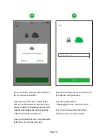
The Communication Board
within the
Inverter
Wire
-B
ox
RS485 Port
1
Inverter Wire-Box
1.
Remove the (3) screws that attach
the inverter
C
ommunication
B
oard in
the Wire-Box using a #2 Phillips bit.
2
2.
Replace the screws with the
(3) standoffs included in the
Flex Gateway Kit.
6-PIN Header
6-PIN Connector
3
3.
Install the Flex Gateway by
carefully aligning the 6-PIN header in
the upper left-hand corner of the
C
ommunication
B
oard.
Install the (3) screws into the stand-offs
to secure the Flex Gateway in place.
Install the 3 screws and torque to 7 in
-
lbs using a #2 Phillips bit.


