


Pag. 52/53 MT-HC3TK15E1599NP-US 00
SW
O
U
T ext
aux
OUT (C)
MAINS (M)
a2
c3
IN (B)
IN (B)
OUT (C)
a1
a3
UPS 2
c1
UPS 3
IN (B)
UPS 1
(D)
OUT (C)
c2
(A)
ext
SWOUT
ext
SWOUT
(A)
(A)
(A)
5.3
Mains, load and battery connections
Mains, load and battery connections.
All the information contained in the section “Mains, load and battery connections” (page
Errore. Il segnalibro non è
definito.
) in relation to the CPS remains valid with the addition of the information set out below.
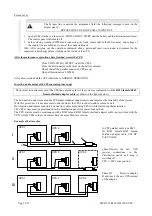
5.3.1 CPS AC input / output power connection
Refer to the INSTALLATION DRAWINGS manual for information on how to select the cable sections for
each CPS
.
Observe the phase connections
Phase L1 of the system must be connected to input phase L1 on all the CPSs; all the output phases L1
must be connected together and with phase L1 of the load. The connections must be observed for phases
L2, L3 and for the input and output neutral.
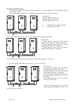
parallel connect the CPS s as follows:
- Connect the power supply phases L1,L2,L3,N to the
corresponding
input phases of each CPS L1,L2,L3,N.
- Connect the load phases L1,L2,L3,N to the
corresponding
output phases of each CPS L1,L2,L3,N.
The figure shows an example of three units connected in parallel.
Power supply line (M)
CPS input terminal boards (B)
CPS output terminal boards Load (C)
Auxiliary SWOUT ext (A)
a1,a2,a3,c1,c2,c3) length of cables
NOTE: “SWOUT ext” must be provided with an auxiliary contact (open with the switch open and closed with the
switch closed).
Length of the cables
The sum of the lengths of the power supply and output cables must be the same for all units. With
reference to the drawing, these must be: a1+c1 = a2+c2 = a3+c3
a = length of input line cables
b = length of output line cables
The same rule must also be observed with separate power lines: the lengths of the cables of the by-pass
line + output line must be the same between all the CPS connected in parallel.
Lack of compliance with this rule may cause a current imbalance between the CPSs when the load is
powered through the by-pass line.
An overload on the by-pass line of one CPS will lead to a deterioration of the components on that line,
both internal and external to the CPS: that is, the disconnector cables and electronic power components.
Содержание C3T
Страница 1: ...CPS C3T 15kVA three phase output User Manual ...
Страница 2: ...Pag 52 53 MT HC3TK15E1599NP US 00 ...
Страница 22: ...Pag 52 53 MT HC3TK15E1599NP US 00 This page is left blank intentionally ...
Страница 32: ...Pag 52 53 MT HC3TK15E1599NP US 00 This page is left blank intentionally ...
Страница 48: ...Pag 52 53 MT HC3TK15E1599NP US 00 This page is left blank intentionally ...


