!
•
-
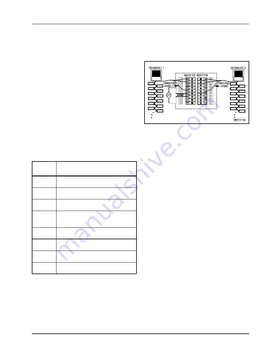
The router is designed to be placed in between Einstein
controllers, typically in the motor room. Figure 5-1 shows
how the router is wired on the Echelon network as a bridge
between an Einstein on one segment and an Einstein on
the other segment.
A router can NOT be placed between an Einstein and
any device that will be associated with the Einstein. In
other words, all devices that are in the same subnet cannot
be separated from each other by a router.
The router has two sets of terminals on the back of its
base plate. Table 5-1 identifies the terminals and their
function.
To hook up a router:
1.
Cut, strip, and connect the three-conductor wires
from Segment 1 to the INCOMING wiring termi-
nals on side A. The two signal wires should be
connected to terminals 1 and 2.
2.
If the router is not the endpoint of the daisy chain
on Segment 1, continue wiring the segment from
side A by connecting the outgoing segment wire
to the OUTGOING terminals 3 and 4.
3.
Connect the bare shield wires on both the
INCOMING and OUTGOING segment wires to
terminal 5 (the ground terminal).
4.
Repeat steps 1 through 3 for Segment 2 on the
outgoing side (side B). Connect the INCOMING
signal wires to terminals 17 and 18, the OUT-
GOING signal wires to terminals 15 and 16, and
the shield wire to terminal 14.
5.
If the physical location of the router is in close
proximity to an Einstein controller, connect a
three-conductor wire in parallel to the Einstein’s
transformer and connect to the router’s terminals
6 and 7. The power inputs are polarity insensitive
and the middle or ground lead should be con-
nected to terminal 5.
A writing space has been included near the wiring ter-
minals for easy field reference while wiring the system.
Use a permanent marker.
Screw
Terminals
Wiring Connections
1 and 2
Incoming network wiring, polarity-insensitive
- CHANNEL A
3 and 4
Outgoing network wiring, polarity-insensitive
- CHANNEL A
5 and 14
Cable Shields - terminals 5 and 14 are inter-
nally connected.
6 and 7
Incoming power wiring, 24VAC, 2.0VA,
polarity-insensitive. Can be powered off the
Einstein 50VA transformer
10 and 12
Unused - Jumpered together internally-may be
used to land extra wires
11 and 13
Unused - Jumpered together internally-may be
used to land extra wires
15 and 16
Incoming network wiring, polarity-insensitive
- CHANNEL B
17 and 18
Outgoing network wiring, polarity-insensitive
- CHANNEL B
Table 5-1
- Router Wiring Terminations
Figure 5-1
- Router Detail Wiring
Содержание Router and Repeater
Страница 1: ...026 1605 Rev 3 9 25 00 Router and Repeater Installation and Operation Manual ...
Страница 2: ......
Страница 4: ......
Страница 16: ......
Страница 22: ......


