


MR Series 600K
User Manual
36
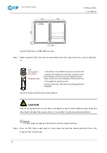
Figure3-9 Bottom size of MR 600K (unit: mm)
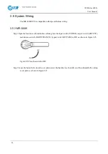
Step 3 Install expansion bolts. The structure and installation for the expansion bolt is as shown in Figure3-
10.
Figure3-10 Expansion bolt structure and installation
Take whole expansion tube into the hole as standard of expansion bolt installation depth. Expansion
tube should not higher than ground, which is to avoid effect the following cabinet installation.
The outer height of expansion bolts should be within the range of 30-50mm.
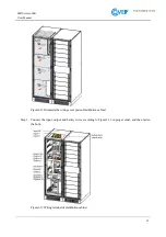
Step 4 Move the UPS from wooden bracket to the ground, and align the bottom installation hole at the
expansion bolt, lock the bolts.
Содержание MR Series
Страница 1: ...Uninterruptible power supply COVER MR 600 kVA User manual ...
Страница 2: ......
Страница 10: ......
Страница 36: ......
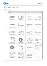
Страница 38: ...MR Series 600K User Manual 28 3 2 Installation Preparation 3 2 1 Installation Tools Tools ...
Страница 56: ......
Страница 60: ...MR Series 600K User Manual 58 Figure4 4 Fault protection with no output Figure4 5 Shutdown ...
Страница 61: ...MR Series 600K User Manual 59 Figure4 6 Exit parallel system Figure4 7 Bypass output ...
Страница 62: ...MR Series 600K User Manual 60 Figure4 8 Battery INV output Figure4 9 Mains INV output ...
Страница 63: ...MR Series 600K User Manual 61 Figure4 10 Grid connected aging running Figure4 11 ECO bypass output ...
Страница 64: ...MR Series 600K User Manual 62 Figure4 12 Frequency conversion INV output Figure4 13 Maintenance bypass output ...
Страница 89: ...MR Series 600K User Manual 87 Figure4 57 Confirm to power off ...


