


MR Series 600K
User Manual
18
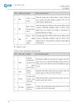
NO.
Name
Illustration
○
,4
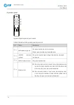
Ready switch
Place the ready switch to “unlock” status, the indication
color is green, the bypass module is not locked with the
cabinet, and at this time, the bypass module can be
dismantled.
Place the ready switch to “lock” status, the indication color
is red, the bypass module is locked with the cabinet, and at
this time, the bypass module cannot be dismantled.
○
,5
Battery start button
At the status of no mains, bypass, press the button for 2s, the
system will start from battery status.
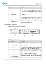
2.5.4 System Control Box
The system control box unit is as shown inFigure2-8.
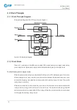
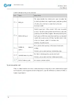
Figure2-9 System control box unit
Table2-4 Illustration for system control box unit
NO.
Name
Illustration
○
,1
Reserved slot position of
expansion card
Install corresponding function expansion card according to
function requirements
○
,2
SNMP card (optional)
It can realize the remote manage for the UPS. Detail operation
and setting please see the user manual of network adapter.
○
,3
System control card
Manage the module output, and control the system parallel
operation and output double busbar synchronization. The
lower is system card 1, The upper is system card 2.
○
,4
System monitor card
Includes communication port, output dry contact and input dry
contact.
Содержание MR Series
Страница 1: ...Uninterruptible power supply COVER MR 600 kVA User manual ...
Страница 2: ......
Страница 10: ......
Страница 36: ......
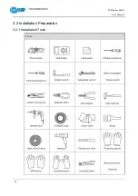
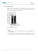
Страница 38: ...MR Series 600K User Manual 28 3 2 Installation Preparation 3 2 1 Installation Tools Tools ...
Страница 56: ......
Страница 60: ...MR Series 600K User Manual 58 Figure4 4 Fault protection with no output Figure4 5 Shutdown ...
Страница 61: ...MR Series 600K User Manual 59 Figure4 6 Exit parallel system Figure4 7 Bypass output ...
Страница 62: ...MR Series 600K User Manual 60 Figure4 8 Battery INV output Figure4 9 Mains INV output ...
Страница 63: ...MR Series 600K User Manual 61 Figure4 10 Grid connected aging running Figure4 11 ECO bypass output ...
Страница 64: ...MR Series 600K User Manual 62 Figure4 12 Frequency conversion INV output Figure4 13 Maintenance bypass output ...
Страница 89: ...MR Series 600K User Manual 87 Figure4 57 Confirm to power off ...


