


17
For additional information email
or call 800-345-6007 M-F 8-5
Operator’s Manual
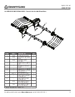
20969 CRT Tiller
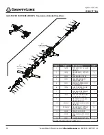
Change Forward Belt
1. Turn off engine. Engine must be cool.
2. Remove spark plug wire and secure from spark plug.
3. Remove belt guard as follows: SEE FIGURE 9
a. Unscrew and remove guard rivet.
b. Pull belt guard from machine.
4. Remove forward belt from engine pulley as follows: SEE
FIGURE 10
a. Gently pull the engine recoil rope to rotate the pulley.
b. With the pulley turning, force the forward belt out of
the V-groove.
c. Slide the belt free of the engine pulley.
d. Pull the forward belt down and out of the way.
5. Install new forward belt as follows:
a. Place forward belt in transmission pulley groove.
b. Gently pull the engine recoil rope to rotate the pulley
while forcing the forward belt into the V-groove.
6. Re-attach belt guard.
7. Attach spark plug wire.
NOTE: Forward Belt Replacement Part # 31315 .
BELT GUARD
BELT GUARD
RETAINING BOLT
20972-0006R1
ENGINE PULLEY
FWD BELT GUIDE
FWD BELT
TRANSMISSION
PULLEY
20972-0007R1
FIGURE 9
FIGURE 10


