CountyLine 20969 Скачать руководство пользователя страница 15

15

For additional information email 

[email protected]

 or call 800-345-6007 M-F 8-5

Operator’s Manual 

20969 CRT Tiller

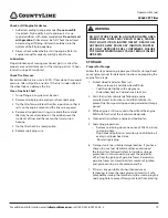
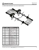
Belt Tension Adjustment
Proper belt tension is critical to good performance. After 1/2 

hour of operation, all cables may have to be adjusted due to 

initial stretch. Thereafter, check tension after every 2 hours 

of operation. Proper tension is achieved when the spring 

compresses 6.4 mm (1/4”) when drive lever is engaged. 
Tools Required for Assembly:
 

13 mm wrench

To increase belt tension: 

1.  Loosen upper jam nut. SEE FIGURE 8
2.  Tighten the lower jam nut in 1/8” increments, making 

sure not to over adjust the tension.

3.  Check adjustment by measuring spring compression 

when drive lever is engaged. (Proper spring compression 

6.4 mm (1/4”))

4.  When proper adjustment is achieved, tighten upper jam 

nut.

This procedure can be repeated until conduit adjustment bolts 

are fully adjusted. If no more adjustment can be made the belt 

may need to be replaced.

Tilling Tips
The key to successful tilling is to begin with a shallow cut on 

the first pass, and then work an inch or two deeper on each 

successive pass.

• 

Tilling depth will vary with ground conditions. 

• 

When beginning to till in unbroken ground or in 

extremely hard soil, set the lock pin in the highest 

hole of the depth regulator lever (SEE OPERATION 

SECTION). This will allow for shallow tilling. With the 

depth regulator lever in this position, make several 

light passes over the area to be tilled. Reset for deeper 

depths with successive passes.

• 

If tiller jumps or skids uncontrollably, lower the depth 

regulator lever by placing the lock pin in a higher 

hole. This will allow for shallower tilling. Hold firmly to 

the handle bars to control sudden lurches.

Immediately release the drive control lever if the tines jam or 

you strike a foreign object. With drive control lever in neutral 

position, push throttle control to stop position to stop the 

engine. Disengage the spark  plug wire. When tines have 

stopped, remove foreign objects and check for damage.

Cultivating Tips
If you plan to use your tiller for cultivating:

• 

Plant rows on 20” - 22” centers for ease of turning.

• 

Set the depth regulator lever with the lock pin in 

one of the higher holes. This will allow for shallow 

cultivation necessary to turn over weeds, and break 

up and aerate the soil.

DRIVE SAFETY CONTROL LEVER

(NEUTRAL)

TENSION NUT

FORWARD CABLE

LOWER JAM NUT

UPPER JAM NUT

SPRING

20972-0008R1

FIGURE 8

PRACTICE SAFETY AT ALL TIMES.  
ENGINE MUST BE TURNED OFF AND ALLOWED TO 

COOL.
SPARK PLUG WIRE MUST BE DISCONNECTED 

AND SECURED BEFORE ATTEMPTING ANY 

MAINTENANCE OR REPAIR.
FAILURE TO COMPLY WITH THIS SAFETY 

REQUIREMENT CAN RESULT IN SERIOUS INJURY 

OR DEATH TO PERSONEL.

        WARNING

ALWAYS MAINTAIN CONTROL OF YOUR TILLER. ONLY 

OPERATE TILLER IN SOIL CONDITIONS THAT ARE 

CONDUCIVE TO MAINTAINING CONTROL OF THE 

TILLER. DO NOT OPERATE TILLER IN CONDITIONS 

THAT CONTAIN ROCKS, FOREIGN OBJECTS, OR 

ANY OTHER MATERIAL THAT IS NOT SOIL. IF YOUR 

TILLER BUMPS, JERKS OR LURCHES, LET GO OF THE 

HANDLE BARS AND THE DRIVE CONTROL LEVERS 

IMMEDIATELY SO THAT THE TINES AND WHEELS 

STOP TURNING. FAILURE TO COMPLY WITH THIS SAFETY 

REQUIREMENT CAN RESULT IN SERIOUS INJURY OR 

DEATH TO PERSONEL.

        WARNING

SRT

CRT

  DANGER

Содержание 20969

Страница 1: ...tor s Manual 20969 CRT Tiller PN 21124 ECN 10568 REV1 11 15 2014 2014 Ardisam Inc All Rights Reserved Email for more information info ardisam com CAUTION ICON R1 READ OM ICON R1 PRODUCT 20969 20972 00...

Страница 2: ...OPERATION AND MAINTENANCE The owner must be certain that all the product information is included with the unit This information includes the MANUAL the REPLACEMENT PARTS and the WARRANTIES This infor...

Страница 3: ...ult in serious injury or death Operate the machine according to the safety instructions outlined here and inserted throughout the text Anyone who uses this machine must read the instructions and be fa...

Страница 4: ...er s instructions for proper operation and installation of accessories Only use accessories approved by the manufacturer Operate only in daylight or good artificial light Do not operate product when f...

Страница 5: ...WSINESS DIZZINESS AND CONFUSION IF YOU EXPERIENCE ANY OF THESE SYMPTOMS SEEK FRESH AIR AND MEDICAL ATTENTION IMMEDIATELY WARNING HOT GASES ARE A NORMAL BY PRODUCT OF A FUNCTIONING INTERNAL COMBUSTION...

Страница 6: ...t go of the handle bars and do not restrain the machine Take all possible precautions when leaving the machine unattended Disengage all control levers stop the engine wait for all moving parts to stop...

Страница 7: ...onal questions contact CountyLine customer service Part No 17051 DANGER WARNINGS Hood Flap Decal Part No 17052 MOVING PARTS WARNING Frame Near Belt Decal A Warning B Avoid Injury From Rotating Tines C...

Страница 8: ...sam com or call 800 345 6007 M F 8 5 FEATURES CHOKE RECOIL START ON OFF THROTTLE CONTROL WHEEL WHEEL LOCK PIN BELT GUARD TINES SIDE SHIELD TINE HOOD LOCK PIN DEPTH REGULATOR LEVER HANDLEBAR FORWARD DR...

Страница 9: ...Cut open seems of carton exposing all contents and remove machine by a Attaching loose wheels in box onto machine with wheel lock pins in free wheel position Slide wheel all the way onto the axle and...

Страница 10: ...e bar mount together Attach Tine Side Shields 1 Locate side shields SEE FIGURE 3 2 Take one side shield raise it up against one side of the tine guard and hold in place 3 Place a M6 flat washer onto t...

Страница 11: ...tank to provide space for expansion See your engine manual for fuel recommendations 5 Be sure spark plug wire is attached and spark plug is tightened securely 6 Check position of wheels and wheel lock...

Страница 12: ...ne when tilling is not being performed Lowering the engine speed to idle will help extend the life of the motor as well as conserve fuel and reduce the noise level of the equipment Operating Speed For...

Страница 13: ...or lever to position tines at chosen tilling depth 3 Align hole in depth regulator lever with hole in depth regulator bracket and insert lock pin Depth Regulator Lever Down Shallower tilling Place the...

Страница 14: ...ole in axle with hole in wheel hub SEE FIGURE 7 2 Insert lock pin through both holes fold lock pin ring to secure pin to axle 3 Repeat for other wheel NOTE Always have both wheel lock pins in or out D...

Страница 15: ...tiller jumps or skids uncontrollably lower the depth regulator lever by placing the lock pin in a higher hole This will allow for shallower tilling Hold firmly to the handle bars to control sudden lur...

Страница 16: ...olong its life and help you obtain optimum performance Please read this normal care schedule and note the recommended care operating intervals to extend the life of your unit Maintenance Operation Pag...

Страница 17: ...ine recoil rope to rotate the pulley b With the pulley turning force the forward belt out of the V groove c Slide the belt free of the engine pulley d Pull the forward belt down and out of the way 5 I...

Страница 18: ...el 4 Remove the gear case dipstick located between the handle bar mounts and the engine mount SEE FIGURE 11 5 Insert the dipstick cut out created in step 1 into the hole in the transmission cover plat...

Страница 19: ...afe place before storing the rototiller unit Be sure to plug the spark plug hole to prevent foreign material from entering Check or Fill Engine Crankcase 1 Add oil according to engine manual Do not ov...

Страница 20: ...p See engine manual to check and adjust throttle linkage Tiller moves forward during starting Drive safety control levers must be released to neutral position to start the engine Tiller is difficult t...

Страница 21: ...her than those indicated in the product s operator s manual alteration accident use of unauthorized parts failure to perform periodic maintenance as specified in product s operator s manual normal wea...

Страница 22: ...onal information email info ardisam com or call 800 345 6007 M F 8 5 ILLUSTRATED PARTS BREAKDOWN MOTOR MOUNT 4 21 5 1 2 3 14 10 9 34 33 36 28 31 35 6 29 30 32 37 2 11 12 8 3 19 17 7 16 18 19 22 20 21...

Страница 23: ...LK TAB BELT GUARD SUPPORT COMPACT RT BLACK 1 19 W1265V0900 NUT M8 X 1 25 HNYLK GR8 8 ZN 10 20 11946 BOLT M6 X 1 0 X 45 HHCS GR8 8 ZN 1 21 20148 WASHER M6 X 18 X 1 6 FLAT ZN 3 ITEM PART DESCRIPTION QTY...

Страница 24: ...0 X 1 5 X 25 HH FCS 2 6 20167 CABLE REAR TINE M5 M8 1016MM SHEATH 1 7 4620 NUT M8 X 1 25 HJAM GR8 8 ZN 2 ITEM PART DESCRIPTION QTY 8 53620 SPRING COMPRESSION FORWARD ARM 1 9 11393 NUT M5 0 8 X 4 4 MM...

Страница 25: ...25 For additional information email info ardisam com or call 800 345 6007 M F 8 5 Operator s Manual 20969 CRT Tiller NOTES...

Страница 26: ...tional information email info ardisam com or call 800 345 6007 M F 8 5 ILLUSTRATED PARTS BREAKDOWN Transmission Tines Hood 20845 0001R1 21 1 2 3 23 26 20 23 22 27 2 25 5 4 27 2 27 14 11 16 24 17 2 18...

Страница 27: ...K ZN HIGH COLLAR 2 10 W1265V0903 NUT M10 X 1 5 HNYLK GR 8 8 ZN 2 11 21018 TIRE WHEEL ASSEMBLY WHITE 10 LUG 12 DEEP 2 12 13601 KNOB M8 BLACK THREE STAR 1 13 53655 WELDMENT DRAG STAKE CRT TILLER DEC 200...

Страница 28: ...X 1 5 SPRLCK ZN 6 3 20133 REAR BEARING CAP NP 1 4 20132 GASKET BEARING CAP FRONT REAR NP 2 5 20137 BEARING TAPERED 20MM ID X 47MM OD 2 6 19993 SHAFT DRIVE CRT SHORT 54 C TO C 20 PA NP 1 7 CAST REAR T...

Страница 29: ...4 3 20138 SNAP RING 25MM EXTERNAL 4 4 SHIM 37 MM X 26 MM X 2 MM 4 5 BUSHING 25 X 32 X 36 5 MM NP 4 6 SHIM 26 X 32 X 1 5 MM NP 4 7 SETSCREW M6 X 1 0 X 8 5 SDP GR8 8 BLK OX 4 8 1500P113 KEY WOODRUFF 5X...

Страница 30: ...Tiller 30 For additional information email info ardisam com or call 800 345 6007 M F 8 5 DO NOT OVERFILL FULL ADD DO NOT OVERFILL FULL ADD DO NOT OVERFILL FULL ADD DO NOT OVERFILL FULL ADD CARDBOARD S...

Страница 31: ...31 For additional information email info ardisam com or call 800 345 6007 M F 8 5 Operator s Manual 20969 CRT Tiller NOTES...

Страница 32: ...223 E mail info ardisam com Distributed by Tractor Supply Co 5401 Virginia Way Brentwood TN 37027 www TractorSupply com All weights specifications and features are approximate and are subject to chang...

Отзывы: