


D.
Within twelve inches (305 millimeter) of an unventilated soffit.
E.
Less than twelve inches (305 millimeter) above grade level from the bottom of the vent terminal.
A vent shall not terminate directly above a side-walk or paved driveway which is located between two
single family dwellings and serves both dwellings.
Clearance of 12" (30cm) minimum is only permitted if the veranda, porch, deck, or balcony, is fully open
on a minimum of 2 sides beneath the floor.
For USA installations, follow current National Fuel Gas Code ANSI Z 223.1 with reference to NFPA 54
(natural gas) or NFPA 58 (propane.) In CANADA refer to CGA B149 Installation Codes Note: Local
Codes or Regulations may require different clearances.
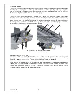
SNORKEL VENT
For installations requiring a vertical rise on the exterior of the building, follow the same installation
procedures as used for standard Horizontal Terminations up to STEP 3, then continue with STEP 4 below.
If the Snorkel Termination must be installed below grade, use the 36" snorkel. Proper drainage must be
provided to prevent water from entering the Snorkel Termination.
Note: The maximum 90 degree elbows permitted per side wall (horizontal)
installation is one. An additional 45 degree is permitted for corner installation.
VERTICAL VENT
Vertical termination assumes no horizontal run of exhaust pipe is involved in the venting system. The
maximum vertical rise allowed for the Bayvue DV appliance is 34 feet when
measured from the top of the
appliance to the bottom of the Flue Cap. The maximum number of 45 degree elbows permitted for a
vertical installation is four elbows. Installation of the four elbows does not decrease the allowable vertical
rise of the Bayvue DV appliance.
STEP 1
Do not pack air spaces between combustibles and the vent pipe with insulation.
STEP 2
Set the gas appliance in the desired location. Drop a plumb bob down from the ceiling to the
position of the appliance flue exit, and mark the location where the vent will penetrate the
ceiling. Drill a small hole at this point. Next, drop a plumb bob from the roof to the hole
previously drilled in the ceiling. Mark the spot where the vent will penetrate the roof.
Determine if ceiling joists, roof rafters, or other framing will obstruct the venting system. You
may wish to relocate the appliance to avoid cutting load-bearing members.
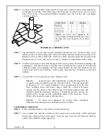
STEP 3
To install the round support box/wall thimble in a flat ceiling, cut a 10" square hole in the
ceiling, centered on the hole drilled in STEP 2. The hole should be of sufficient size to meet the
minimum requirements of 1" to combustibles. Frame the hole as shown in FIGURE 16.
STEP 4
If the twist-lock adapter has not been installed on the stove by the manufacturer; install it now in
accordance with the stove instruction manual.
Version 1.0h
30
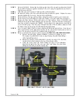
STEP 5
Assemble the desired lengths of black pipe necessary to reach from the appliance adapter up
through the round support box. Insure that all pipe and elbow connections are in their fully
twist-locked position.
Содержание Bayvue DV 30
Страница 48: ...SAFETY LABEL Version 1 0h 47...