background image


18 

3.3 Communication Settings 


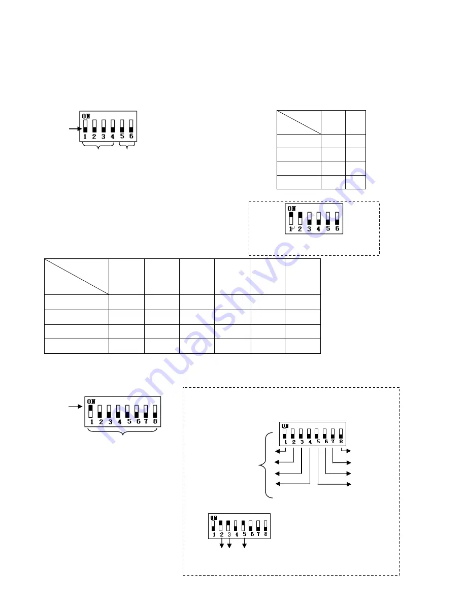
Before  installation  and  use,  the  unique  address  for  each  dome  and  the  communication  protocol  including 
transmission speed (baud rate) should be set to correspond with the chosen control system.   

3.4 


Setting the Protocol and baud rate settings for each dome device.


CAUTION: 

The protocol and baud rate of dome device 

should match the settings of the controller. In order to take 
effect the dome must be power cycled after each change. 


3.5


Address setting of each dome

. To prevent damage, each dome must have a unique address (ID). 


Dome device range: 0~255. 


            On/Off 

Baud rate 

5

th


digit 

6

th


digit   

2400 

OFF 

OFF 

4800 

OFF 

ON 

9600 

ON 

OFF 

19200 

ON 

ON 

                On/Off     

status 

Protocol type 

1

st

 digit 

2

nd


digit 

3

rd


digit 

4

th

 digit 

5

th


digit 

6

th

 digit 

PELCO-D 

ON 

ON 

OFF 

OFF 

** 

** 

PELCO-P 

OFF 

OFF 

ON 

OFF 

** 

** 

Auto Detect 

OFF 

OFF 

OFF 

OFF 

** 

** 

System reserve 

ON 

ON 

ON 

ON 

** 

** 


This example illustrates PELCO-D 

protocol and Baud rate of 2400. 
 

Setting  address  for  dome  device 
(this figure shows the address of 
dome device No 1). 

O

n/O

ff s

w

itc

h


Setting method:

 The sum of switch numbers in the ON 

position is the address of the dome device. (Binary Method) 


Calculation example   
of dome device address: 


16 

32 

64 

128 


16 

2+4+16=22

the dome address is: 

22


O

n/o

ff 

sw

itc

an

m

atc

hin

g n

um

be

rs 

O

n/O

ff D

ip

 sw

itc

B

au

d r

ate

 se

ttin


Pr

oto

co

l s

ett

in

Содержание CDC2500MI

Страница 1: ...odel No CDC2500MI Model No CDC2500MXO Indoor Version Outdoor Version Costar Video Systems 2720 Commodore Drive Suite 150 Carrolton TX 75007 Tel 972 446 8844 Fax 972 446 8866 Please read this manual thoroughly before use or installation and keep it handy for future reference Rev M080415 ...

Страница 2: ...1 THIS PAGE IS INTENIONALLY LEFT BLANK ...

Страница 3: ...ower to the dome before attempting any operations or adjustments inside the dome cover to avoid potential damage to the mechanism 3 Inside the dome cover there are precision optical and electrical devices Heavy pressure shock and other sudden adjustments or operations should be avoided Otherwise you may cause irreparable damage to the product 4 Please DO NOT remove or disassemble any internal part...

Страница 4: ...AY CAUSE HARMFULL INTERFERENCE TO RADIO COMMUNICATIONS OPERATION OF THIS EQUIPMENT IN A RESIDENTIAL AREA IS LIKELY TO CAUSE HARMFULL INTERFERENCE IN WHICH CASE THE USER WILL BE REQUIRED TO CORRECT THE INTERFERENCE AT HIS OWN EXPENSE CAUTION CHANGES OR MODIFICATIONS NOT EXPRESSELY APPROVED BY THE PARTY RESPONSIBLE FOR COMPLIANCE COULD VOID THE USER S AUTHORITY TO OPERATE THE EQUIPMENT THIS CLASS A ...

Страница 5: ...n any way when liquid traces are present or the presence of loose objects is evident or if the device does not function properly or has received sever impact or has been dropped accidentally 13 Indoor dome is for indoor use only and not suitable for outdoor or high humidity locations Do not use this product under circumstances exceeding specified temperature and humidity ratings 14 Avoid pointing ...

Страница 6: ...te of dome device 18 3 5 Address setting of each dome 18 4 Chapter 4 Quick Start Operation Guide 4 1 Wiring 19 4 2 Setting protocol and baud rate 19 4 3 Setting the device address 20 4 4 Connect the power to the dome 20 4 5 Joystick controller setting 20 4 6 Start testing 20 4 7 Complete the test Summary 20 5 Chapter 5 Program and Operation 5 1 Main menu 21 5 2 Tree Menu List 22 5 2 1 Language Opt...

Страница 7: ... of the controller only on power up Continuous Pan 360 degree rotation slip ring 90 degree Tilt action plus 2 degree angle adjustment the view angle can be 90 or 92 degrees Pan speed in manual operation is variable from 0 1 up to 300 degrees per second Tilt speed in manual operation is variable from 0 1 to 120 degrees per second 128 preset positions A preset position is defined as a user definable...

Страница 8: ...mable privacy zones sectional mask User can mask part of the camera sectors which differs between different models of installed cameras Eight sectors of user programmable sectional display User can define and display the name and position of the camera which differs between different models of installed cameras Resume automatic operation after initial self test of the dome as well as resume automa...

Страница 9: ...eo harness 1 24VAC transformer optional 1 Wall bracket optional 1 Instruction manual 1 Camera Ribbon cable spare 1 Figure 1 Illustrates the upper layer of the packing material top half Figure 2 Illustrates the lower layer of the carton bottom half Fig 1 Fig 2 Acrylic Dome Cover Manual Quality certificate Spare camera ribbon cable Cable Harness and connectors 24 VAC 2 Amp Transformer Wall Bracket S...

Страница 10: ...ould you need to replace the cable that connects the camera module to the control board Figure 3 below illustrates the wiring configuration of the flex ribbon cable Fig 3 Step 1 Insert FFC Socket of the cable to the relevant port of the base plate on the dome control board as illustrated in Figures 4 and 5 Fig 4 Fig 5 Cable Connector Camera ribbon cable Push the tab back in to secure the camera ca...

Страница 11: ...rated in Figure 6 according to the model and make of the camera as different camera models may have different dimensions Following the installation of the camera module verify that it does not touch any of the dome parts including the camera shroud and acrylic dome by gently moving the camera module along the vertical axis Fig 6 Fig 7 Step 3 Insert the other end of the ribbon cable to the correspo...

Страница 12: ...10 Fig 11 Step 1 Position the open end of the camera shroud towards the camera lens as illustrated on Figure 11 Align the 4 holes of the shroud with the 4 holes on the motor support of the dome as illustrated in Figure 12 Step 2 Utilizing the supplied 4 four M3 5 screws securely tighten the camera shroud in place as illustrated in Figure 12 Fig 12 Screw holes of camera shroud Tighten the screws ...

Страница 13: ... the wall bracket to the wall verifying that the surface you are attaching to can support the weight of the dome using either expanding anchors or butterfly fasteners as illustrated in Figure 14 Fig 14 Note Different bracket options may be available Illustrations are for reference purposes only and may vary from actual package contents depending selected installation options at time of order Feed ...

Страница 14: ...seals Please verify that they are in place and securely positioned as illustrated in Figure 15 2 In between the bracket and the dome there is a weatherproofing seal made from a spongy material as illustrated in Figure 16 Make sure that it is firmly attached to the dome upper surface as it will prevent any water from entering into the dome electronics In contrast with the outdoor model the seal for...

Страница 15: ...era Step 1 Carefully align the two parts as illustrated in Figure 17 Slowly rotate counterclockwise until a small click is felt indicating the beginning of the threads Step 2 Slowly start rotating the bottom part clear acrylic in a clockwise direction without forcing the threads as illustrated in Figure 18 It takes approximately three 3 complete rotations to have a complete seal Fig 17 Fig 18 Step...

Страница 16: ...tration of the wiring diagram for the electrical connections to the dome unit Fig 20 Figure 21 illustrates the wiring harness included with the dome Fig 21 Yellow Green Ground Wire Video output 24V power supply Black Red Yellow Orange Yellow Green Ground Wire Connect to control keyboard Yellow green Ground Video output BNC Connector Orange RS485 Yellow RS485 Red Black 24VAC power supply Connect to...

Страница 17: ...llustration JMP 120R is the impedance matching selection of control signal and noise restrain of RS 485 When the dome control is done over long cable run or there is a need for noise limiting you need to install this jumper provided together with the set of screws For normal runs up to 500 feet no action is required Caution This operation should be performed with the power removed Power OFF Grounf...

Страница 18: ...utput from joystick controller connected in a bus configuration to the RS485 communication terminals of the control cable for each dome Video Signal output from the dome camera connected to a monitor DVR or video matrix Take into consideration impedance matching and or termination Joystick Controller CCTV Monitor Power Supply AC24V Video CCTV Monitor Power Supply AC24V Video CCTV Monitor Power Sup...

Страница 19: ...device range 0 255 On Off Baud rate 5th digit 6th digit 2400 OFF OFF 4800 OFF ON 9600 ON OFF 19200 ON ON On Off status Protocol type 1st digit 2nd digit 3rd digit 4th digit 5th digit 6th digit PELCO D ON ON OFF OFF PELCO P OFF OFF ON OFF Auto Detect OFF OFF OFF OFF System reserve ON ON ON ON This example illustrates PELCO D protocol and Baud rate of 2400 Setting address for dome device this figure...

Страница 20: ...re illustrates Auto detection protocol Baud rate 2400 bps Baud rate 2400bps Note This dip switch is located on PCB in the control board just below the camera module Protocol setting Baud rate setting Protocol setting Baud rate setting CCTV Monitor Wiring Harness RS 485 RS 485 AC24V AC24V VIDEO VIDEO Controller Power Supply Keyboard of controller Dome Power Supply OD CONNECT V3 Grounding Grounding ...

Страница 21: ...d controller can be set arbitrarily But its baud rate should be set identical with that of the dome device 4 6 Start testing When all of the above settings are completed you can start testing to dome functionality 1 Direction control test of dome device 2 Zooming control test of camera Please refer to the next section for demonstration of menu operation and control of dome device 4 7 Complete the ...

Страница 22: ...he Up or Down direction The on screen arrow points to the selected option Using the joystick to the Left or Right position you can change the value of your selection or enter the submenu for the selected option 3 Press CLOSE Iris Close to exit menu or return to the previous menu one layer up 1 Language English 2 Display Options 3 Control Options 4 Diagnostic Options 5 Camera Options 6 Function Pro...

Страница 23: ... position location and return to the previous menu level 3 Call Preshot Call preshot Based on the displayed selected preset position on line 1 of this menu the dome will respond upon moving the joystick to the Right position and move to the corresponding coordinates of the selected preset position 4 Delete preshot Delete preshot Caution Are you sure you want to delete preset Press OPEN to confirm ...

Страница 24: ...ne Joystick Left or Right when programming to select preshot and press OPEN to confirm Joy stick left or right to select 0 9 or A Z Press OPEN to confirm selection Press CLOSE to exit or return to the previous menu level when programming is done Joystick Left or Right to select Joy stick Left or Right to select Press OPEN or Joy stick Left or Right to enter Setup pan start point Press OPEN or Joys...

Страница 25: ...Default function On Off Joystick Left or Right to select 3 Speed Limit ON OFF Operation speed limit On Off Joystick Left or Right to select 4 Auto Flip ON OFF Auto flip On Off Joystick Left or Right to select 5 Auto Focus PTZ OFF Z Auto focus options Joystick Left or Right to select 6 Auto AE PTZ OFF Z Auto AE option Joystick Left or Right to select 7 Vector Scan AF ON OFF Vector scan auto focus c...

Страница 26: ...igh Low Auto focus sensitivity setting High Low Joystick Left or Right to select 2 Auto Exposure Auto exposure setting Press OPEN or Joystick Left or Right to enter 1 AE Mode Auto Manual Shutter Iris Auto exposure mode Joystick Left or Right to select 2 Shutter Speed xx Shutter speed setting Joystick Left or Right to select 3 Iris Fxx Iris setting Joystick Left or Right to select 4 Gain x Gain set...

Страница 27: ...ight to select 8 Picture LR Rev ON OFF Picture left and right reverse Joystick Left or Right to select 9 Picture Stable ON OFF Picture stabilized On Off Joystick Left or Right to select 10 Day Night ON OFF Black white and color switch On Off Joystick Left or Right to select 11 F OSD ON OFF Camera function display On Off Joystick Left or Right to select _ _ _ _ _ _ _ _ 0 1 2 3 4 5 6 7 8 9 A B C D E...

Страница 28: ...k Left or Right to select 2 Program a Vector scan Vector scan programming Press OPEN or Joystick Left or Right to enter _ _ _ _ _ _ _ _ 0 1 2 3 4 5 6 7 8 9 A B C D E F G H I J K L M N O P Q R S T U V W X Y Z _ IRIS CLOSE When Done IRIS OPEN to Begin IRIS CLOSE to Exit Call out Are you sure to do this IRIS OPEN to Confirm IRIS CLOSE to Cancel Joystick left or right when programming to select presho...

Страница 29: ... to upper stage P V T 1 128 0 0 1 2 3 4 5 6 7 8 9 IRIS CLOSE When Done N Y Name Num E N Press OPEN continuously to select P Preshot T self learn V vector scan Joy stick Left or Right when programming to select preshot and press OPEN to confirm Joy stick Left or Right to select 0 9 Press OPEN to confirm selection Press CLOSE to exit or return to upper stage Press OPEN continuously to select Joy sti...

Страница 30: ... SHOT ACK Start Vector Scan 5 88 SHOT ACK Start Vector Scan 6 89 SHOT ACK Joy sticks between freeze and unfreeze video 90 SHOT ACK Setup the Menus and Camera 91 SHOT ACK Invokes the Flashback Function PreShot 92 93 94 Reserve for future options Power 24VAC 1 0 Amp for indoor 2 0 Amp for outdoor Power Consumption 18W without camera Weight 6 5 lbs 3Kg without camera Installation Method Wall Ceiling ...

Страница 31: ...ot displayed Fault of OSD control board Replace OSD board After self test the menu can be displayed only when there is Video image on the monitor Interference caused by external electronic signals noise or the camera video format is set incorrectly NTSC PAL Ground the dome device or identify and reduce the external interference electric motors HF high power fluorescent lamps or reposition the came...

Страница 32: ...per connection of control cable polarity Verify the polarity of the RS485 connection as per the instruction manual Follow installation instructions Maximum Communication cable run is exceeded Add amplification circuit for RS485 Intermittent or incorrect connections Verify the wiring Slip ring is damaged Replace the slip ring 10 Intermittent control of dome device RS 485 protective discharge arrest...

Страница 33: ...tional mode The flip feature is useful when you need to track someone who walks directly beneath the dome and continues on the other side IR MODE A feature of the camera that permits manual or automatic switching between color and IR black and white operation When IR mode is active clearer images may be obtained under low light conditions LINE LOCK Allows you to phase lock the video with the AC po...

Страница 34: ...ultaneously and linearly WDR Wide Dynamic Range Technology uses two shutter speeds in alternative video fields high and normal every 60th or 50th of a second and combines two fields into one progressive scan frame It allows every detail to be captured accurately even if one portion of an image is brilliantly Whether at the high shutter speed or normal shutter speed the progressive scan CCD provide...

Страница 35: ...34 Printed in the USA Rev M080415 ...

Отзывы: