7
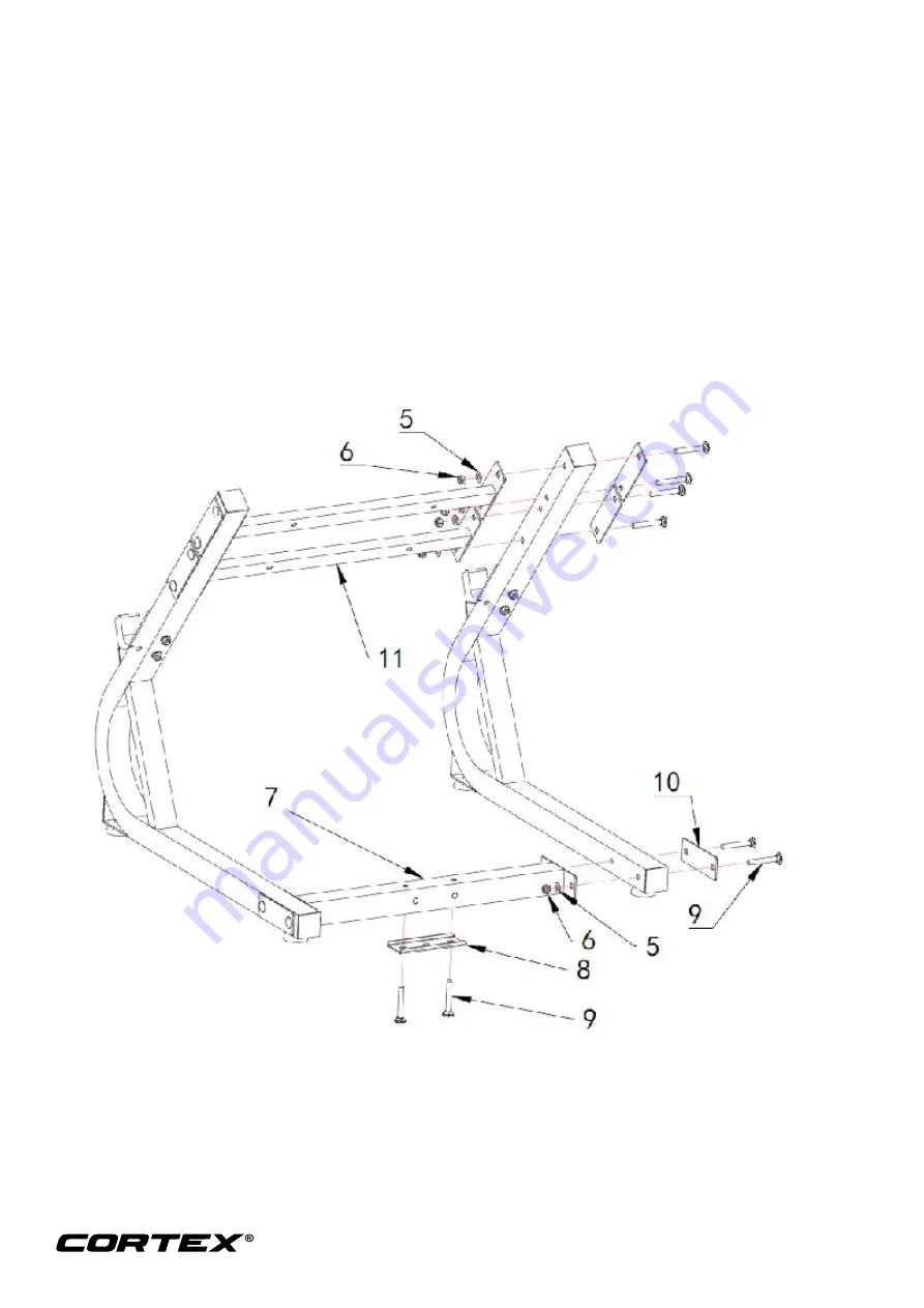
Step 2
1. Install the bottom connection frame (# 7) with the 50mm connection plate (# 8), as shown, and
then screw on the nut with the carriage bolts M10 * 70 (# 9) through the bottom connecting frame
(# 7).
2. According to the diagram, the main bend frame (# 1) is placed on one end of the bottom
connecting frame (# 7) and fastened with 110 flat connecting plate (# 10), carriage bolt M10x70
(# 9), flat gasket (# 5) and nut (# 6); The other end is the same.
3. The upper connecting frame (# 11) is placed between the two main bending frames (# 1) as
shown, and then the connection plate (# 10), the carriage bolt M10 * 70 (# 9), the flat gasket
(#5), and the nut (# 6) are fastened with the 110mm flat connecting plate (# 10).
4. The other upper connecting frame (# 11) is the same as the other upper connecting frame (#11).
Содержание BH-8
Страница 5: ...5 3 PARTS LIST ...


