


Electrical Component
Checking
Blower Motor
General Information
The blower used in the blend air HVAC system is a
brushless DC motor (BLDC). The front control unit
(FCU) or auxiliary control unit (ACU) provides a DC
voltage signal to the motor to control speed. This
eliminates the need for a resistor block as used on
the water-valve controlled HVAC system. The blower
motor provides a feedback signal to the FCU or ACU
to indicate blower speed and error conditions.
Delayed Speed Change
When the blower speed is changed on the control
panel, a delay in actual speed change is normal. The
speed will ramp up or down at 1000 rpm per second.
Therefore, if the fan is off and then turned on high
speed, it will take approximately six seconds for the
fan to actually reach full speed.
Starting Sequence Protection Mode
In case the blower motor does not start (the feed-
back line indicates zero speed), the FCU or ACU will
apply five consecutive starting sequences. If all five
starting sequences are unsuccessful, the blower
motor electronic module enters a starting sequence
protection mode. The module will no longer attempt
to start the blower motor until the control signal from
the FCU or ACU is reset to zero. See "Blower Motor
Stall Protection Mode." This means one of the follow-
ing must occur:
•
Turn the blower speed switch to the off posi-
tion, then back on.
•
Cycle the ignition switch.
•
Disconnect/reconnect the blower motor con-
nector.
Possible reasons the blower motor may enter the
starting sequence protection mode include:
•
locked blower motor rotor
•
open circuit in blower motor feedback signal
line
•
faulty blower motor
Temperature Protection Mode
The blower motor has an internal temperature sensor
connected to the blower motor electronic module.
The electronic module monitors the blower tempera-
ture and enters a protection mode when normal tem-
perature is exceeded. When the blower motor enters
protection mode, the blower speed is reduced to
1000 rpm to reduce the load on the motor. When the
motor temperature has lowered to the normal range,
the blower speed resumes operation according to the
control panel settings.
If the temperature continues to rise or remains too
high after the blower speed is initially reduced, the
speed is further reduced to minimum speed (about
400 rpm) and then the blower motor stops. Once the
blower motor temperature returns to normal, the
blower speed resumes operation according to the
control panel settings. No reset is required.
Blower Motor Voltage Protection
Mode
The blower motor electronic module monitors the
voltage supply to the motor and enters a protection
mode when the voltage is too high or too low. The
protection mode works as described in
Blower Motor Stall Protection Mode
The blower motor electronic module monitors the
blower for a locked rotor condition. If the rotor is
locked starting from an off condition, the electronic
module will attempt a starting sequence before enter-
ing this protection mode. See "Starting Sequence
Protection Mode." If the blower rotor locks up and
stalls from a running condition, the blower will imme-
diately enter this protection mode. The blower motor
will not restart until the blower speed control signal
has decreased to minimum by cycling the ignition, or
turning the blower speed control from ON to OFF,
then back to ON, and the stall condition has disap-
peared.
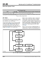
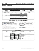
Speed/Diagnostics Feedback Line
The blower motor supplies diagnostic and speed in-
formation to the FCU/ACU. See
and
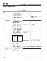
Heater and Air Conditioner Troubleshooting
83.00
Electrical System Tests
122SD and Coronado Workshop Manual, Supplement 9, June 2014
330/1