background image

19

MAINTENANCE SECTION

DISASSEMBLY

General Instructions

1. Do not disassemble the tool any further than

necessary to replace or repair damaged parts.

2. Whenever grasping a tool or part in a vise, always use

leather--covered vise jaws to protect the surface of the
part and help prevent distortion. This is particularly
true of threaded members and housings.

Always use leather--covered vise jaws when
clamping the handle in a vise. Leather will
conform to the shape of the handle and allow the
tool to be held securely. To prevent damage to the
exhaust diffuser, never clamp only the bottom of
the handle.

3. Do not remove any part which is a press fit in or on

a subassembly unless the removal of that part is
necessary for repairs or replacement.

4. Do not disassemble the tool unless you have a

complete set of new gaskets and O--rings for
replacement.

Disassembly of the Impact Wrench

1. Clamp the handle of the impact wrench in a vise with

leather--covered jaws with the square driver
positioned horizontally.

Avoid excessive clamping pressure which can
damage the Housing and can cause difficulty when
removing the parts.

2. Unscrew and remove the four Hammer Case Screws

(11).

3. While lightly tapping on the end of the Anvil (8) with

a plastic hammer, lift off the Hammer Case (15) and
Hammer Case Gasket (18).

The Front End Plate (2) might come off during the
removal of the Hammer Case. Make sure that it
does not drop on the floor or strike a hard or
metallic surface since it might be damaged.

4. Grasp the Hammer Frame (12) and carefully lift off

the entire impact mechanism, making certain not to
drop the two Hammer Pins (13).

Disassembly of the Impact Mechanism

1. Set the mechanism, driver end up, on the workbench.

Note the twin hammers within the Hammer
Frame. These are identical, but must be placed in
the Hammer Frame in a certain relationship. Using
a felt--tipped pen, mark

he top “T

” hammer and

the bottom hammer “B

” with the arrows

pointing upward. Mark both Hammers on the

same end.

2. With the mechanism sitting upright on the workbench,

slowly rotate the Anvil in a clockwise direction until
it comes up solid.

If you continue to rotate the Anvil, it will cam the
Hammers out of engagement. Don’t do this; merely
rotate the Anvil until it comes up solid.

3. Hold the Hammer Frame firmly and without

disturbing the hammers, gently lift the Anvil while
simultaneously rotating it clockwise about 1/8 of a
turn, from the Hammer Frame.

4. With the Anvil removed, lift out the two Hammer

Pins.

The twin hammers are now free to slide from the
Hammer Frame. Be careful do not to drop them.

Disassembly of the Motor

When pulling, disassembling or assembling the
motor, we recommend replacement of the Motor
Gasket (7).

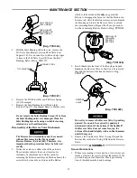
1. Remove the Motor Assembly from the Housing (19)

by pushing on Power Management Dial (35) from the
back of the Housing. Refer to Dwg. TPD1322.

POWER

MANAGEMENT

DIAL

(Dwg. TPD1322)

Содержание IR-C2131

Страница 1: ...efore performing any maintenance on this tool Do not lubricate tools with flammable or volatile liquids such as kerosene diesel or jet fuel Use only recommended lubricants Keep work area clean unclutt...

Страница 2: ...malfunctioning tool or accessory Do not modify the tool safety devices or accessories Do not use this tool for purposes other than those recommended Use accessories recommended by Ingersoll Rand Note...

Страница 3: ...he forward direction only The Air Wrench will always operate at maximum power output in the reverse direction no matter what power output level is selected The four power setting indicators of increas...

Страница 4: ...C18 03 FKG0 28 For International use Unit Number C28 C3 FKG0 Do not mark any nonmetallic surface on this tool with customer identification codes Such actions could affect tool performance Dwg TPD905...

Страница 5: ...s que le k ros ne le gasoil ou le carburant d aviation Utilisez seulement les lubrifiants recommand s Maintenez le lieu de travail propre sans obstruction a r et bien clair Ne retirer aucune tiquette...

Страница 6: ...l N utilisez jamais un outil ou accessoire endommag ou de fonctionnement douteux Ne modifiez jamais l outil les dispositifs de s curit ou les accessoires N utilisez pas cet outil des fins autres que c...

Страница 7: ...m la puissance maximum en marche avant seulement La cl pneumatique fonctionnera toujours la puissance maximum en desserrage quel que soit le niveau de puissance s lectionn ATTENTION Les quatre indicat...

Страница 8: ...TISSEMENT Do not mark any nonmetallic surface on this tool with customer identification codes Such actions could affect tool performance Plan TPD905 2F F L R TUYAUTERIE PRINCIPALE AU MOINS 3 FOIS LA D...

Страница 9: ...o combustible para motores a reacci n Use nicamente los lubricantes recomendados Mantenga la zona de trabajo limpis despejada ventilada e iluminada No saque ninguna etiqueta Sustituya toda etiqueta d...

Страница 10: ...e nunca una herramienta o un accesorio da ado o que no funcione correctamente No modifique la herramienta los dispositivos de seguridad ni los accesorios No utilice esta herramienta para otros fines q...

Страница 11: ...cia m xima en el sentido de giro a derechas solamente La llave neum tica siempre funcionar con la m xima potencia en el sentido inverso cualquiera que sea el nivel de potencia seleccionado AVISO Los c...

Страница 12: ...nguna superficie no met lica de esta herramienta con los c digos de identificaci n del cliente Tal acci n podr a afectar al rendimiento de la herramienta ESPECIFICACIONES Modelo Tipo de empu adura Acc...

Страница 13: ...zer manuten o na mesma N o lubrifique a ferramenta com l quidos inflam veis ou vol teis como querosene gas leo ou combust vel para jactos Utilize apenas os lubrificantes especificados Mantenha a rea d...

Страница 14: ...edicamentos Nunca utilize uma ferramenta ou acess rio avariado ou a funcionar mal N o modifique a ferramenta os dispositivos de seguran a ou os acess rios N o utilize esta ferramenta para fins diferen...

Страница 15: ...m nima at pot ncia m xima apenas na direc o de avan o A Chave Pneum tica funcionar sempre pot ncia m xima na direc o de invers o independentemente do n vel de pot ncia seleccionado ADVERT NCIA Os quat...

Страница 16: ...CUIDADO N o marque nenhuma superf cie n o met lica desta ferramenta com c digos de identifica o do cliente Isto poderia afectar o desempenho da ferramenta Desenho TPD905 2P F L R LINHAS PRINCIPAIS 3...

Страница 17: ...et 2131 283 19 Housing Assembly C2131 D40 8 Anvil Assembly 19A Nameplate C2131 301 1 2 square drive 231C A626 19B Warning Label WARNING 2 99 9 Socket Retainer 231 425A 20 Inlet Bushing Assembly 2131 5...

Страница 18: ...ve Seat mechanism 115 1LB Retainter Grease for lubrication when 27 Inlet Retainer Clip 2131 57 disassembling and assembling 28 Trigger Assembly 2131 A93 the impact mechanism 2A Trigger O ring 1 lb 105...

Страница 19: ...ome off during the removal of the Hammer Case Make sure that it does not drop on the floor or strike a hard or metallic surface since it might be damaged 4 Grasp the Hammer Frame 12 and carefully lift...

Страница 20: ...Plate on a flat nonmetallic surface such as a work bench This will loosen the Front Rotor Bearing so that it will drop out of the Front End Plate Refer to Dwg TPD1323 Dwg TPD1323 FRONT END PLATE FRON...

Страница 21: ...ed screwdriver used for removing the Forward and Reverse Buttons Insert the screwdriver between the partition and the Button which is fully extended Gently pry against the Button to disengage the dete...

Страница 22: ...Reverse Valve are facing downward Refer to Dwg TPD1330 EARS Dwg TPD1330 Use a wooden dowel to push the Reverse Valve up through the handle until the top of the Reverse Valve is flush with or slightly...

Страница 23: ...g Refer to Dwg TPD1473 Dwg TPD1473 Inlet Bushing Screen Installation Tool 2 Install the Washer 1A Inlet Retainer Clip 27 Inlet Bushing Seal 1B Tilt Valve Spring 1C Tilt Valve 1D Tilt Valve Seat 1E and...

Страница 24: ...sert the Motor Assembly into the Housing 19 Power Management Dial end first Assembly of the Impact Mechanism TOP HAMMER HALF ROUND NOTCH ON RIGHT BOTTOM HAMMER HALF ROUND NOTCH ON LEFT Dwg TPD1535 1 C...

Страница 25: ...at in the Housing If the Hammer Case Gasket is not installed correctly the Air Wrench will not function properly Refer to Dwg TPD1335 1 4 Apply a thin film of Ingersoll Rand No 105 1LB Grease or Inger...

Страница 26: ...in a clean suit able cleaning solution in a well ventilated area Assemble the Tool and inject 3 cc of the recommended oil into Inlet and run Tool to lubricate internal parts Damaged Reverse Valve Rep...

Страница 27: ...27...

Страница 28: ...0402...

Отзывы: