


I ns t al l at i o n C MA - XX X- A E N
P a ge 4 1
Draft
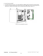
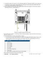
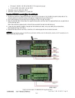
3. Push PEM back in slot and close captive screws.
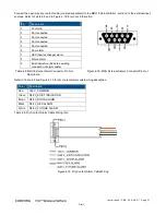
4. Identify the positive and negative terminals for the DC pair to be wired on the CLASS1 connector feed positions. The
wiring sequence is positive to positive and negative to negative.
5. Use a wire-stripping tool to remove the covering from the end of the DC wire pairs.
6. Open the terminal block screw above the negative feed position and then insert the exposed black wire (negative feed)
into the terminal block.
Note: Ensure that no exposed portion of the DC wires extends from the terminal block plug.
7. Torque the terminal block captive screw (above the installed wire lead), using a ratcheting torque screwdriver.
Recommended torque is 0.49N•m.
8. Repeat the same process as in Step 6 and Step 7 for remaining positive feed (exposed red wire).
CAUTION! Secure the wires coming in from the terminal block so that they cannot be disturbed by casual contact. For
example, use tie wraps to secure the wires to the rack.
4.8
Verifying Normal Operation
•
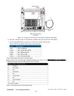
Verify that all the fans are operational.
•
By referring to Table
2-2. MRU LED Description, verify that all the LEDs on the top-left of the chassis door and on each
PAM are signaling normal system operation.


