


I ns t al l at i o n C MA - XX X- A E N
P a ge 3 2
Draft
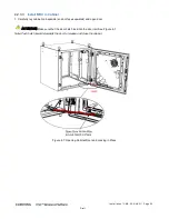
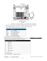
7. Connect RF antenna coax - (for both 4.3-10 Type “ANTENNA PORT” and “2.5GHz INPUT PORT”) route coax cable with
90
◦
right angle connector through its’ designated knockout (see Figure
4-6) behind and above the MRU chassis and
connect to the corresponding RF port. Refer to Figure
4-11.
8. Route optic fiber from ICU and power cable through designated knockouts (see Figure
4-6) and connect according to
instructions in section
4.4. Refer to Figure
4-11.
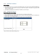
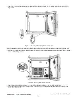
Figure
4-11. Example of Routed Connection Cables
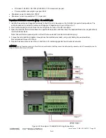
Note: For DC power connections – route DC power cable with open wires (without connector) and then wire according to
instructions in section
4.7.2.
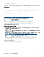
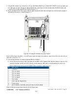
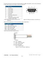
9. Perform external alarm connections between MRU and cabinet:
A. Connect the external alarms cable (provided with the MRU) to the chassis’s DB-9 ‘External Alarms’ connector. The
connector provides indications for door opening, heat exchanger (HEX) and one additional input for future use.
Refer to Table
4-5 and to Figure
4-12 for MRU ‘External Alarms’ connector pin out.
Pin
Description
1
Common
2
Not connected
3
Not connected
4
Not connected
5
Not connected
6
Door alarm
7
HEX (heat exchange) alarm
8
Future alarm
9
Exist indication (indicates existing connection of alarm cable)
Table
4-5. MRU External Alarm Connector Pin Out Description


