STANDARD RECOMMENDED PROCEDURE 009-221 | ISSUE 8 | AUgUST 2015 | PAgE 8 OF 10
7.3.1 Routing Cable
Step 1:
Install connectors on the fibers per instructions provided with the connectors.
Step 2:
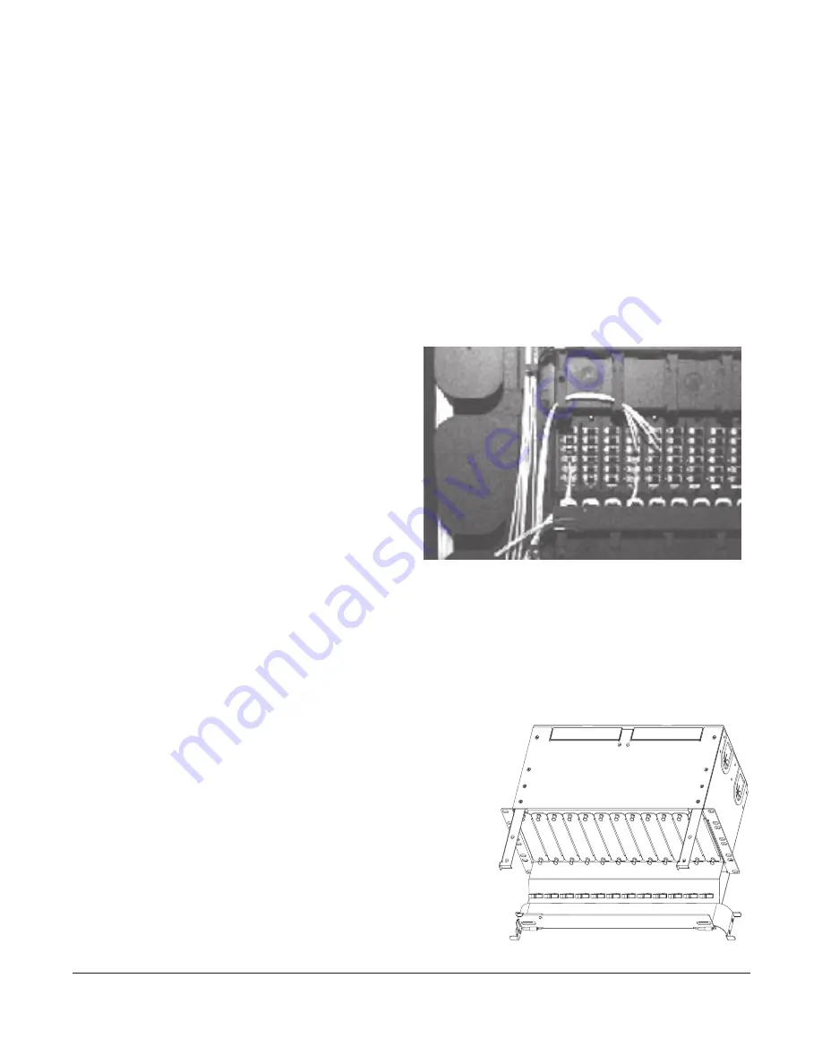
Route the fiber slack inside the housing in the pattern shown in Figure 13.
Step 3:
Clean the adapters and connector end-faces per standard company practices or as
described in Section 9; then plug the connectors into the adapters at the rear of the
connector panels.
Step 4:
If routing pigtails to the housing, attach an identification tag to the end of each
bundle, indicating the number of the panel to which it is attached. Pigtail fibers can
be routed through the pass-through ports in the top and bottom of the housing to
splice hardware in splice shelves.
Step 5:
Attach a numerical identification tag to each tight-buffered fiber, indicating the
connector location on the panel.
NOTE:
If it is necessary to remove any excess length of spiral-wrapped fiber, make sure to place new
identification tags on the new working length prior to removing the excess.
7.3.2 Install Jumpers
In the CATV environment where moves,
adds, and changes are frequent, good
jumper management and record keeping
are imperative. To help maintain a neat and
organized installation, Corning strongly
recommends the use of the Jumper
Management Panel and the Inter-Bay Storage
Unit (Figure 14) (contact your Corning
Optical Communications customer care
representative for assistance).
If using the jumper management panel, route
jumpers through the management panel and down into the C4U housing (Figure 14). Otherwise,
route jumpers into the housing from either side over the jumper trough (Figure 15), or in through
the ports in the floor of the housing (Figure 16).
NOTE:
Allow the minimum bend radius when inserting the jumpers into the routing clip and routing the
jumpers out of the housing. Do not apply more pulling force to the cable than specified. Do not
use the clip when routing to a jumper management panel above the C4U housing.
7.3.3 Jumper Management Using
Jumper Trough
Step 1:
Install jumper trough in the front of the housing
using the two screws provided (Figure 15).
Step 2:
Route jumpers through the routing clip
below the applicable adapter panel. Or route
jumpers through the jumper management
panel as shown in Figure 14.
Step 3:
Clean the adapters and connector end-faces.
Mate the connectors in the adapters.
KPA-2204
Figure 14
KPA-2202
Figure 15


