CoreTigo TigoBridge B1 Скачать руководство пользователя страница 16

TigoBridge B1 

User Manual


Copyright © 2021 CoreTigo Ltd.


Page 

16

 of 

21


8. 

Diagnostics and Troubleshooting  

Troubleshooting is done using the LEDs display or the TigoEngine software. Refer to TigoEngine User 
Manual for detailed instructions.  

8.1.  Power LED 

Power LED 

– if a power supply is connected to the TigoBridge B1 and the Power LED is off, the power 

supply is not properly connected, or it is providing a power supply different than the expected range. 

8.2.  Status LED 

Status LED 

– indicates the IO-Link device connection status and the IO-Link Wireless communication 

status with the IO-Link Master. Therefore, it alternates to show both the status of the IO-Link device 
connection and the IO-Link Wireless connection.  

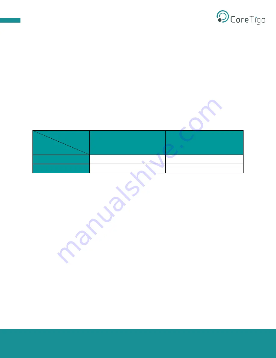
Table 3: Status LED troubleshooting 

        IO-Link Wireless                                   


Wired IO-Link 

Paired 

Unpaired 

Operational 

Alternating Blue and Green 

Alternating Magenta and Green 

Non-Operational 

Alternating Blue and Yellow 

Alternating Magenta and Yellow 


Alternating Blue and Green


– fully Operational: both IO-Link device and IO-Link Wireless 

communication properly functioning.  

Alternating Magenta and Green


– TigoBridge B1 is unpaired from the TigoMaster while the IO-Link 

device is properly connected to the TigoBridge B1. Re-Scan and Re-Pair the TigoBridge B1 to the 
TigoMaster through the TigoEngine.  

Alternating Blue and Yellow 

– TigoBridge B1 is successfully paired to the TigoMaster while the IO-Link 

device is not properly connected to or not fully functioning with the TigoBridge B1. Check the IO-Link 
device connectivity with the TigoBridge B1.  

Alternating Magenta and Yellow


– Both TigoBridge B1 IO-Link Wireless communication are unpaired 

and the IO-Link device is not connected/functioning. Power down the TigoBridge B1 and power it back 
up, reconnect the IO-Link device, scan, and pair the TigoBridge B1. 

Содержание TigoBridge B1

Страница 1: ...TigoBridge B1 User Manual Copyright 2021 CoreTigo Ltd Page 1 of 21 CoreTigo TigoBridge B1 USER MANUAL...

Страница 2: ...cription 9 4 2 Overview 9 4 2 1 Functional Diagram 10 4 3 LEDS 10 4 3 1 Power LED 10 4 3 2 Status LED 11 4 4 Pair by Button 11 4 5 Electrical Wiring 11 4 6 Electrical Connection 12 5 Mounting 12 5 1 T...

Страница 3: ...re 7 Cradle Dimensions 12 Figure 8 TigoBridge B1 and Cradle 13 Figure 9 TigoBridge B1 Mounted on the Cradle 13 Figure 10 TigoEngine Scanning Mode 14 Figure 11 TigoEngine Pairing Process 14 Figure 12 T...

Страница 4: ...igo Ltd Page 4 of 21 Acronyms and Abbreviations Acronyms and abbreviations used in this document are listed in this table Symbol Meaning FW Firmware HW Hardware IF Interface IOLW IO Link Wireless LED...

Страница 5: ...ce to IO Link Wireless as long as it is IO Link certified Read the manual carefully before using the device Figure 1 TigoBridge B1 References TigoEngine User Manual TigoMaster 2TH User Manual 1 1 Stru...

Страница 6: ...B1 shall be supplied by an isolated power source that meets the following requirements Limited Energy Circuit in accordance with UL CSA 61010 1 or Limited Power Source LPS in accordance with UL CSA 60...

Страница 7: ...must be demonstrated under all the following circumstances Safety and health at work Mounting and connecting of electrical equipment Measurement and analysis of electrical functions and systems Evalua...

Страница 8: ...B1 is part of an IO Link Wireless environment It communicates with an IO Link Wireless master Therefore to use it you need an IO Link Wireless master IO Link device and a power cable See the illustra...

Страница 9: ...le TigoBridge B1 can be connected to an IO Link Wireless Master by TigoEngine Integrated web server tool or PLC Each IO Link Wireless master can operate up to 16 TigoBridges 4 2 Overview Figure 3 Tigo...

Страница 10: ...Figure 4 TigoBridge B1 Functional Diagram A Device Connector B Pairing Button C Power Supply Connector D Power LED Green E Status LED RGB 4 3 LEDS Figure 5 TigoBridge B1 LEDs A Status LED RGB B Power...

Страница 11: ...a new one The TigoBridge B1 must be powered off to assure that the TigoMaster disconnects before installing a new TigoBridge B1 Pairing Button currently disabled To enable contact CoreTigo Support 4...

Страница 12: ...5 Mounting TigoBridge B1 should be mounted safely and securely next to the device to which it is connected TigoBridge B1 can be mounted with or without the cradle accessory 5 1 TigoBridge Cradle The...

Страница 13: ...onnected to PC Installation 1 Plug a 24VDC power supply to TigoBridge B1 M12 power connector via M12 cable 2 The Power LED lights up green If it does not check the power connection 3 Once the power su...

Страница 14: ...ted TigoBridge B1 Select an empty port on the Master side and click Pair Figure 11 TigoEngine Pairing Process 8 When the pairing process is complete the TigoEngine Port Mode should indicate OPERATE Th...

Страница 15: ...tton on the TigoEngine interface and repeat the instructions to unpair it Once unpaired the TigoBridge B1 status LED alternates between magenta and green Figure 14 Unpair Button 7 Firmware Update Firm...

Страница 16: ...perational Alternating Blue and Green Alternating Magenta and Green Non Operational Alternating Blue and Yellow Alternating Magenta and Yellow Alternating Blue and Green fully Operational both IO Link...

Страница 17: ...ation of this equipment in a residential area is likely to cause harmful interference in which case the user will be required to correct the interference at his own expense 9 3 Modification Statements...

Страница 18: ...es LEDs IO Link RGB three color LED Power Green color LED Button Pairing external push button Connectors Input connector Plug M12 A coded power Connector o Pin number 1 Input 1L Power supply o Pin num...

Страница 19: ...from a limited Class 2 power supply or via overcurrent protective device fuse breacker etc rated 3A max For 24 VDC Supply input without IO Link device current consumption For 30 minutes To read more a...

Страница 20: ...TigoBridge B1 User Manual Copyright 2021 CoreTigo Ltd Page 20 of 21 Block Diagram Dimensions 11 Customer Support For any issue question or to report a bug contact support coretigo com...

Страница 21: ...x A Part Number Part number CT231 0057 01 Generation 1 Product Identifier 3 Product Type 1 Protocol 0057 Character Identifier of Feature Version 01 CT GXY ZZZZiii vv 1 3 1 0057 iii 01 Generation Produ...

Отзывы: