


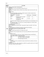

2C9
1-4-33
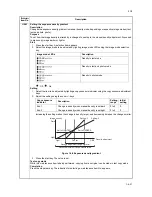
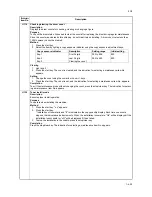
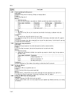
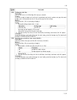
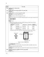
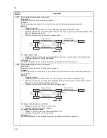
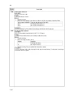
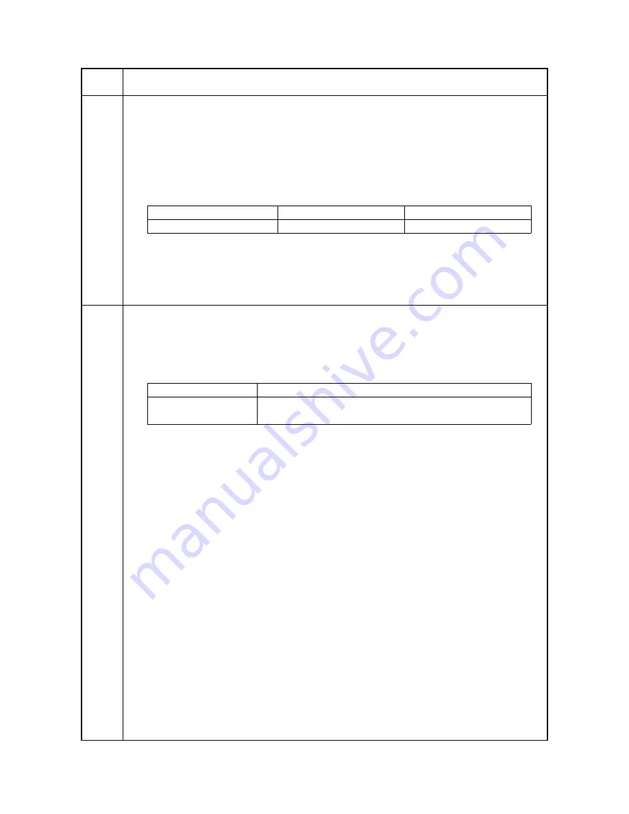
U255
Setting auto clear time
Description
Sets the time to return to initial settings after copying is complete.
Purpose
To be set according to frequency of use. Set to a comparatively long time for continuous copying at the same
settings, and a comparatively short time for frequent copying at various settings.
Method
Press the start key. The current setting is displayed.
Setting
1. Change the setting using the zoom +/- keys.
The setting can be changed by 10 s per step.
When set to 0, the auto clear function is cancelled.
2. Press the start key. The value is set, and the indication for selecting a maintenance item No. appears.
Completion
To exit this maintenance item without changing the current setting, press the stop/clear key. The indication for
selecting a maintenance item No. appears.
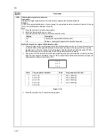
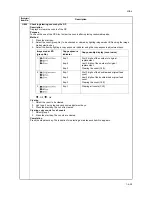
U258
Switching copy operation at toner empty detection
Description
Selects if continuous copying is enabled after toner empty is detected.
Method
Press the start key. The current setting is displayed.
Setting
1. Select single or continuous copying using the zoom +/- keys.
Initial setting: Sin
2. Press the start key. The setting is set, and the indication for selecting a maintenance item No. appears.
Completion
To exit this maintenance item without changing the current setting, press the stop/clear key. The indication for
selecting a maintenance item No. appears.
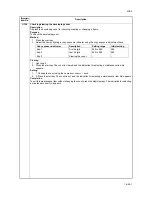
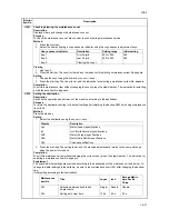
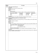
Maintenance
item No.
Description
Description
Setting range
Initial setting
Auto clear time
0 to 270 (s)
90
Display
Description
Sin
Enables only single copying.
Con
Enables single and continuous copying.
Содержание CS-1620
Страница 1: ...SERVICE MANUAL Published in June 05 2C970946 Revision 6 CS 1620 2020...
Страница 4: ...This page is intentionally left blank...
Страница 10: ...This page is intentionally left blank...
Страница 48: ...2C9 4 1 4 7 This page is intentionally left blank...
Страница 61: ...2C9 4 1 4 18 This page is intentionally left blank...
Страница 73: ...2C9 4 1 4 28 This page is intentionally left blank...
Страница 84: ...2C9 4 1 4 37 This page is intentionally left blank...
Страница 94: ...2C9 4 1 4 45 This page is intentionally left blank...
Страница 147: ...2C9 4 1 6 16 This page is intentionally left blank...
Страница 173: ...2C9 6 0 1 6 40 This page is intentionally left blank...
Страница 235: ......


