


2
Refer to the PLC catalog for discharge wall proximity
factors.
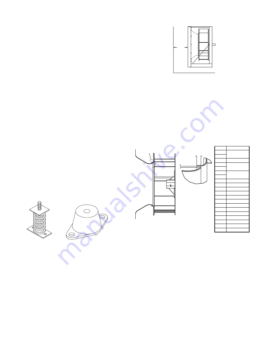
Wheel-to-Inlet Clearance
The correct wheel-to-inlet clearance is critical to proper
fan performance. This clearance should be verified before
initial start-up since rough handling during shipment could
cause a shift in fan components. Refer to wheel/inlet draw-
ing for correct overlap.
Adjust the overlap by loosening the wheel hub and mov-
ing the wheel along the shaft to obtain the correct value.
A uniform radial gap (space between the edge of the
cone and the edge of the inlet) is obtained by loosening the
inlet cone bolts and repositioning the inlet cone.
Wiring Installation
All wiring should be in accordance with local ordinances
and the National Electrical Code, NFPA 70. Ensure the
power supply (voltage, frequency, and current carrying
capacity of wires) is in accordance with the motor name-
plate.
Lock off all power sources before unit is wired to power
source.
Leave enough slack in the wiring to allow for motor
movement when adjusting belt tension. Some fractional
motors have to be removed in order to make the connec-
tion with the terminal box at the end of the motor. To
remove motor, remove bolts securing motor base to power
assembly. Do not remove motor mounting bolts.
Minimum
1 wheel
diameter
Figure 2 - Non-ducted Inlet Clearance
Wheel/Inlet Overlap
Size
Overlap
120
.250
135
150
.313
165
.375
180
195
.438
210
225
.500
245
.563
270
.625
300
.688
330
.625
365
.688
402
.750
445
.875
490
.938
540
1.063
600
1.108
660
1.313
730
1.438
See Detail A
Overlap
Radial Gap
Detail A
Isolation
Isolation Base
If supplied, mount the fan on the rigid isolation base that
runs the entire length of the fan base angle.
When the motor is not an integral part of the unit, mount
the fan and its motor to a common rigid base running the
full length of the fan and motor.
The base must have sufficient rigidity to resist belt pull
and prevent drive distortion which can lead to excessive
belt and bearing wear. Isolators should be located between
this rigid base and the floor.
NOTICE! Although a certain amount of vibration is
inherent in operating centrifugal fans, extreme vibra-
tion is a serious problem that may cause structural and
mechanical failure.
Isolators
Floor Mounted Spring Isolators
• Mount fan and motor on an isolation base (if supplied).
• Elevate fan (or isolation base) to operating height and
insert blocks to hold in position.
• Position isolators under the fan and/or isolation base
and vertically align by inserting leveling bolt through
mounting holes in the fan or the base. The isolator
must be installed on a level surface.
• Adjust the isolators by turning the leveling nut counter
clockwise several turns at a time alternately on each
isolator until the fan weight is transferred onto the isola-
tors and the fan raises uniformly off the blocks. Then
remove the blocks.
• Turn lock nut onto leveling bolt and secure firmly in
place against the top of the mounting flange or frame.
• Secure isolators to mounting surface.
Floor Mounted Rubber-In-Shear (RIS) Isolators
• Mount fan and motor on an isolation base (if supplied).
• Elevate fan to provide room to insert isolators between
base and foundation or between the fan and foundation
and block in position.
• Position isolators under isolation base or fan and
secure bolts.
• Remove blocks and allow unit to rest on floor. Isolators
must be installed on a level surface (leveling should not
be required).
• Secure isolators to mounting surface.
Duct Installation
Efficient fan performance relies on proper installation.
If the fan has an open inlet (no duct work), be sure it is
placed one fan wheel diameter away from walls and bulk-
heads. Refer to
figure 2
.
Rubber-In-Shear Isolator
Spring Isolator
Figure 1 - Floor Mount Isolators