CONTROLS, INCORPORATED
C O N T R O L S Y S T E M S & S O L U T I O N S
- 3 -
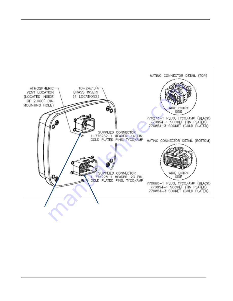
MODULE CONNECTORS
Primary Connector
14 Pin
Secondary Connector
23 Pin
Страница 1: ...G7230 AS Revision 1 2 ______________________________________________________________________________________________________________________________________ Copyright Controls Inc P O Box 368 Sharon...
Страница 2: ...PIN CONNECTOR PANEL CONNECTOR 5 21 PIN ENGINE HARNESS CONNECTOR FLOAT CONNECTOR 6 ENGINE ALARMS CODES AND MESSAGES 7 WARNINGS ALARMS ALARM EVENT LOG INDICATION LAMPS CONTROL PANEL SPECIFIC ALARMS AND...
Страница 3: ...start wire is not grounded SLEEP MODE To minimize current draw the panel goes into a sleep mode two minutes after being set in auto mode In sleep mode the display goes blank and the red lamp blinks on...
Страница 4: ...CONTROLS INCORPORATED C O N T R O L S Y S T E M S S O L U T I O N S 3 MODULE CONNECTORS Primary Connector 14 Pin Secondary Connector 23 Pin...
Страница 5: ...y 1 Common 13 Fuel Level 7 J1939 High 14 High Float Input SECONDARY CONNECTOR 23 Pin Pin Function Pin Function Pin Function 1 Relay 5 9 Relay 5 6 Common 16 Relay 6 2 N A 10 N A 17 Low Float Input 3 N...
Страница 6: ...onnector Pin Function B Battery Positive E Battery Negative G Key On Power D Crank Signal V J1939 High U J1939 Low J Alternator Excite L Analog Throttle Emulator M Analog Throttle Emulator C Analog Th...
Страница 7: ...rol panel Note Must use normally open contacts of the floats Controller will start engine when floats are closed Engine will stop upon float circuit opening SINGLE FLOAT Pin Function 1 Float Common 2...
Страница 8: ...essage appears on the display identifying the cause ALARM EVENT LOG The Alarm Log creates an entry allowing the service and or operator to view the last 32 events An event is considered either a warni...
Страница 9: ...CONTROLS INCORPORATED C O N T R O L S Y S T E M S S O L U T I O N S 8 INDICATION LAMPS The panel has two lamp indicators Engine Fault Shutdown Lamp Engine Warning Lamp...
Страница 10: ...s Pre Alarm 15 0 100 PSI Low Oil Press Alarm 10 0 100 PSI Oil Press Alarm Delay 5 0 01 1 40 Sec Temperature Check Run Off Always Run Low Temp Pre Alarm 0 0 300 Deg F Low Temp Alarm 0 0 300 Deg F High...
Страница 11: ...tion Alarm Polarity Positive Initial State Off Relay 4 Function Crank 21 Pin Connector D Polarity Positive Initial State Off RELAY FUNCTIONS Available relays can be assigned for different uses a None...
Страница 12: ...orn Energizes an external audible alarm when an alarm condition is present Pressing the ENTER button will silence l Low Oil Press Alarm Relay closes if a low oil pressure shutdown is detected m High C...
Страница 13: ...ntervals will automatically be incremented to the Next Service Warning Interval and the Next Service Required Interval as programmed into the controller After resetting the interval the controller wil...
Страница 14: ...nu Auto Start Delay Default 10 seconds Pre Heat Time Default 0 seconds Crank Time Default 10 seconds Crank Rest Time Default 10 seconds Warm Up Speed Default 800 rpm Warm Up Time Default 10 seconds Pr...
Страница 15: ...the menu options Press the UP arrow button to enter menu Press the DOWN arrow button to reverse Exit Menu System Hold the MENU button and press the ENTER button To Change a Setting Press the ENTER but...
Страница 16: ...Load Torque Oil Temp etc Engine Identification View Engine Model and Serial Module Information Menu Control Unit Part View Control Unit Software Version View Controller Setup Menus Input Configuration...
Страница 17: ...to Fuel Run Relay Output 3 Pre Set to Alarm Relay Output 4 Pre Set to Crank Relay Output 5 Setup Function Polarity Initial State Relay Output 6 Setup Function Polarity Initial State Relay Output 6 Set...
Страница 18: ...m Selection Deg F Default 245 F Engine Temperature Alarm Time Delay Selection Default 0 10 Battery Volt Check Off Run Always Default Off Low Battery Volt Pre Alarm Selection Default 12 0 V High Batter...
Страница 19: ...e Run Time Selection Default 15 minutes Next Recharge Time Interval Selection Default 45 minutes 8 Auto Operation Settings Start Stop Input Floats Transducer Default Floats Throttle Mode Selection Def...
Страница 20: ...00 38400 available Parity Default Odd Stop Bits Default 1 Slave Address Default 1 Enable Gauges Default No Yes to drive MODbus gauges Tachometer Default 0 3000 RPM Engine Oil Temperature Deg F Default...