Unidrive Regen Installation Guide
11
Issue Number: 2
www.controltechniques.com
5.4
Softstart resistor
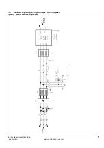
The start-up circuit limits the amount of current flowing into the DC bus of the Regen drive and into the motoring drives.
5.4.1
Single systems
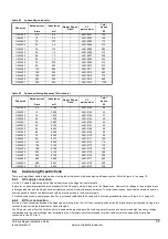
The softstart resistor for single Regen applications must be as specified in the following table. Energy rating and overload are non-standard and both
are important.
Table 5-2
Single Regen, single motoring, Unidrive size 1 to 5
Table 5-3
Softstart resistor data
The above figures have been calculated assuming a peak supply voltage of 480 Vac +10%. Refer also to Appendix B Component Sizing Calculations.
5.4.2
Multiple systems
In non standard cases, e.g. multiple motoring, multiple Regen systems, the soft-start resistor size and rating must be recalculated due to the charging
characteristics changing. For the method of calculating the new resistor size and rating, refer to Appendix B Component sizing calculations on
page 36.
5.4.3
Protection
Protection for the softstart circuit is provided using a thermal overload to protect against a high impedance short circuit, and a separate magnetic
overload to protect against a direct short circuit. For multiple systems the softstart resistor size must be recalculated resulting in resizing of the
thermal magnetic overload required. Refer to Appendix B Component sizing calculations on page 36.
Table 5-4
Thermal magnetic overload
5.5
Contactors, MCBs and overload
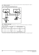
Contactors and MCBs are required as follows:
Table 5-5
Contactors and MCBs
MCB 1x is fitted between the switching frequency filter capacitors and the AC supply. The MCB should have an auxiliary which the enable for the
Regen and motoring drive is connected through. This will act as a safe guard and prevent the system running with a fault on the switching frequency
filter. Also refer to Appendix B Component sizing calculations on page 36.
Drive
size
Number of
parallel resistors
Total value
Resistors
Ω
CT part number
Value
Ω
1
1
150
1270-3157
150
2
1
150
1270-3157
150
3
1
48
1270-2483
48
4
2
24
1270-2483
48
5
2
24
1270-2483
48
Drive size
Resistors
Rms current
A
Charging current
A
1
1270-3157
0.4
5
2
1270-3157
0.4
5
3
1270-2483
0.5
15
4
1270-2483 x 2
0.6
32
5
1270-2483 x 2
1.2
32
Drive size
Rated Current
A
Rated Voltage
Vac
Number of
Poles
CT part number
1 & 2
0.3
480
1
4133-0117
3
1
480
1
4133-0217
4 & 5
2
480
1
4133-0277
Function
Ref
Description
Specification
Main contactor
K2
3 pole NO + auxiliary NO
contact. Coil voltage selected
to suit available supply.
Current rating equal to total current requirement.
Voltage rating equal to AC mains supply voltage.
Auxiliary
contactor
K3
2 pole NC + auxiliary NO
Coil must not exceed 240Vac 5A resistive load.
Installation category 1.
Switching
frequency filter
MCB
MCB
1x
3 pole + auxiliary NC
Current rating sized to rms current of switching frequency filter
capacitors and charging current at power up.
(Refer to Table 5-6).
Thermal
magnetic
overload
Ovld
Single pole
Sized to the softstart resistor to protect thermally and
magnetically. (Refer to Appendix B Component sizing
calculations on page 36).


