12
Unidrive Regen Installation Guide
www.controltechniques.com
Issue Number: 2
5.6
Switching frequency filter
The AC input terminals of a Regen drive produce a PWM output voltage, which has a sinusoidal component at line frequency, plus significant
harmonics at the switching frequency and its multiples.
This filter prevents switching frequency harmonic currents getting back into the supply. If the filter is not fitted, the presence of currents in the kHz
region could cause supply problems or disturbance to other equipment.
N
The switching frequency filter inductors need to be rated to the total current requirement.
The following inductors are standard 3-phase inductors (rated at drive rated current for a single Regen system or rated at total current requirement for
multiple Regen system), they carry only 50/60Hz current with a negligible amount of high frequency current.
The capacitors specified below are suitable for operation at any switching frequency. These capacitors are sized for operation at 3kHz however
operation above 3kHz is possible with the capacitors being more effective.
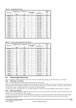
Table 5-6
Switching frequency filter
X
= number of size 5 drives
5.6.1
Protection
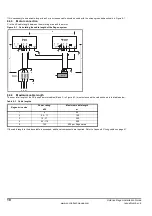
An MCB should be fitted between the AC supply and the capacitor. This is to protect the wiring between the capacitor and the main bus bar.
N
For multiple Regen systems, refer to Appendix B Component sizing calculations on page 36 for sizing of the MCB.
Drive
3-phase inductor
3-phase capacitor
MCB rating
Model
Rated
current
Lfilt
CT part
number
Cfilt
CT part
number
rms
current
Peak
current
A
mH
µ
F
A
A
UNI 1405
9.5
3.160
4401-0162
5.7
1610 - 5752
2.1
28
UNI 2401
12
2.500
4401-0163
31
UNI 2402
16
1.875
4401-0164
36
UNI 2403
25
1.200
4401-0165
45
UNI 3401
34
0.880
4401-0166
24
1665 - 2244
15
106
UNI 3402
40
0.750
4401-0167
115
UNI 3403
46
0.650
4401-0168
124
UNI 3404
60
0.500
4401-0169
142
UNI 3405
70
0.390
4401-0170
160
UNI 4401
96
0.315
4401-0171
48
1665 - 2484
25
252
UNI 4402
124
0.240
4401-0172
262
UNI 4403
156
0.190
4401-0173
325
UNI 4404
180
0.165
4401-0174
348
UNI 4405
202
0.135
4401-0175
385
UNI 5401
300
0.100
4401-0176
80 (x1)
1665 - 2804
35 per
capacitor
580
UNI 5402
600
0.050
4401-0177
80 (x2)
580
UNI 5403
900
0.034
4401-0178
80 (x3)
580
UNI 5404
1200
0.025
4401-0179
80 (x4)
580
UNI 540
X
300 x
X
0.100 /
X
80 (x
X
)
580
NOTE
NOTE

