background image

any equipment. 

¬ 

Disconnect the power cord when the appliance will be idled for a long 
period of time. 

¬ 

Do not

 attempt to service this unit  yourself as  removing  any covers may 

cause exposure to dangerous voltage. 

¬ 

Always route the power cord so that it is not likely to be walked on or 
pinched by other appliances. 

Never 

use extension cords. 

¬ 

Do not

 overload outlets with more than one appliance. This can result in fire 

or electrical shock. 

¬ 

Your model is equipped with a grounded and polarized plug. Do not defeat 
the purpose of this plug by removing the ground post or using a non-
polarized adapter without properly grounding the outlet. 

¬ 

Never connect any appliance to a power source while standing in water or 
with wet hands. 

¬ 

When a replacement part is required, always insist on factory authorized 
parts only. 


MAINTENANCE 

PERIODIC CLEANING PROCEDURE 

It is best to clean your refrigerator or freezer when the product load is at its lowest 
level inside your cabinet. To clean the interior or exterior cabinet surfaces, the 
following procedure should be followed: 
 

1.  Disconnect your model from its power supply and remove all food product from 

inside. 

2.  Open all doors and allow the cabinet to reach room temperature. Remove all 

accessories (shelves, racks, pilasters, clips, etc.) from within the model, wash 
with a baking soda and warm water solution, and rinse thoroughly with clear 
water. Dry all of the accessories completely with a soft clean cloth. 

3.  Once the cabinet has reached room temperature, wash the entire cabinet 

inside and out with a baking soda and warm water solution. For slightly more 
difficult cleanups, ammonia or vinegar in warm water can be used. Rinse 
thoroughly with clear water and dry with a soft clean cloth. Failure to dry all 
surfaces completely may cause water stains or streaking on the aluminum or 
stainless steel finish. 

4.  Return all accessories to their respective positions and return electric supply 

power to the model. 


PRECAUTIONS


1.  Never use harsh detergents, cleaners, scouring powders, or chemicals 

when cleaning your model. 

2.  Strong bleaches tend to corrode many materials and should never come in 


- 20 - 


Содержание Refrigerators and Freezers

Страница 1: ...uction Manual for Reach In Refrigerators and Freezers Continental Scientific A Division of National Refrigeration Air Conditioning Products Inc 539 Dunksferry Road Bensalem PA 19020 5908 215 244 1400...

Страница 2: ...DURE 9 ELECTRICAL CONNECTIONS 9 115 VOLT 60 HZ 1 PHASE CONNECTION 9 208 230 VOLT 60 HZ 1 PHASE CONNECTION 9 SPECIAL VOLTAGE CONNECTIONS 10 START UP CHECKLIST 10 REMOTE APPLICATIONS 10 OPERATION 11 THE...

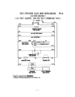
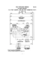
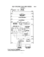
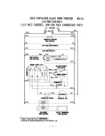
Страница 3: ...TROUBLESHOOTING AND SERVICING GUIDE 22 WIRING DIAGRAMS 26...

Страница 4: ...for the evaporator coil to reach its operating temperature approximately 20 minutes No floor drains or plumbing connections are required since all models are completely self defrosting and use an auto...

Страница 5: ...riod may you lay the model on its back and only then when its properly blocked so as not to crush the condensate drain tubing and also to allow provision for your hands in order to set it in its uprig...

Страница 6: ...es are essential for maximum cooling capacity and long life of refrigeration parts FIGURE 1 MINIMUM CLEARANCE DIMENSIONS FLOOR LOADS The floor at the final location site must be level free of vibratio...

Страница 7: ...e by tilting the cabinet in the opposite direction and install the remaining legs Make sure the legs are tightened extremely well or the entire model will sway or rock with each opening or closing of...

Страница 8: ...il If allowed to continue ice will eventually block the coil and the model will fail This will result in the loss of all product stored within the cabinet 4 Defrost water will fail to drain properly a...

Страница 9: ...ing screws located on the bottom of the cabinet back and install the mounting bracket on the case bottom as shown in figure 4 Slide the condensate pan onto the bracket install the drain tube into the...

Страница 10: ...cedure All doors have been aligned at the factory however vibration during transportation may cause doors to shift and realignment may be necessary If the door s require realignment proceed as follows...

Страница 11: ...ver and remove the thumbscrews securing it in place The thermometer bulb cover is located on the interior top left corner towards the front of the cabinet Once the cover is removed carefully grasp the...

Страница 12: ...uation of 10 of the voltage indicated on the cabinet serial data plate Full voltage of the correct service on an individual line not affected by the operation of other electrical appliances must be av...

Страница 13: ...any unusual noises are heard turn the unit off immediately and check for any obstructions of the condenser or evaporator fans Fan motors fan blades or fan housings can be jarred out of position throug...

Страница 14: ...fied temperature range the exterior thermometer located on the upper grill must be checked for calibration accuracy All thermometers are carefully calibrated at the factory prior to shipping but may b...

Страница 15: ...oint of origin by that many degrees by pressing directly on the mylar display towards the left top If your digital display needed to be decreased you must decrease the point of origin by that many deg...

Страница 16: ...l see figure 6 If an adjustment is necessary to maintain the above temperature range only place a screwdriver into the thermostat slot and turn clockwise for a colder cabinet temperature or counterclo...

Страница 17: ...signed and factory set to maintain an average cabinet temperature of 20 c and 28 c respectively All freezers are designed for the purpose of holding pre frozen bulk product and although they are capab...

Страница 18: ...ow allows access to the timer dial To set the time of day on the defrost time clock turn the knob on the center dial of timer face counterclockwise as the arrows indicate until the correct time of day...

Страница 19: ...ed air evaporator assembly which utilizes a plasticized fin coil for extended life see figure 9 LOW PROFILE CEILING MOUNT EVAPORATOR ASSEMBLY The low profile evaporator system is comprised of a genero...

Страница 20: ...shelf three 3 epoxy coated shelves per section and four 4 epoxy coated shelves per section on glass door models only SHELVING INSTALLATION Pilaster strips which support the shelving are secured to the...

Страница 21: ...o not load product to block back wall leave at least 2 of air space between product and back wall FIGURE 10 STANDARD PILASTER OPTIONAL INTERIOR ACCESSORIES In addition to the optional heavy duty pilas...

Страница 22: ...DUTY PILASTER FIGURE 12 OPTIONAL ANGLE PAN SLIDES SAFETY PRECAUTIONS The following safety precautions should be followed when operating any appliances Always disconnect the power cord before attemptin...

Страница 23: ...To clean the interior or exterior cabinet surfaces the following procedure should be followed 1 Disconnect your model from its power supply and remove all food product from inside 2 Open all doors an...

Страница 24: ...the sliding glass door insert the door in the top track and use it to slide the closing mechanism to the half open position Lift the door so it clears the bottom track push in to align the door with...

Страница 25: ...VICE Always provide the cabinet model and serial number located on the data plate on the inside right wall of the cabinet whenever contacting the factory or your dealer regarding questions or when ord...

Страница 26: ...g unit starts and runs but short cycles on over load protector 1 ADDITIONAL CURRENT PASSING THROUGH OVERLOAD PROTECTOR 2 LOW VOLTAGE TO UNIT 3 OVERLOAD PROTECTOR DEFECTIVE 4 RUN CAPACITOR DEFECTIVE 5...

Страница 27: ...N 5 DEFROST EVAPORATOR COIL 6 DETERMINE LOCATION AND REMOVE 7 CLEAN CONDENSER COIL 8 REPLACE EVACUATE AND RE CHARGE Start capacitor open shorted or blown 1 RELAY CONTACT NOT OPENING PROPERLY 2 PROLONG...

Страница 28: ...EVACUATE AND RE CHARGE 2 OPEN VALVE FULLY OR REPLACE IF NECESSARY Noisy condensing unit 1 LOOSE PARTS OR MOUNTINGS 2 TUBING RATTLE OR VIBRATION 3 BENT FAN BLADE CAUSING EXCESSIVE VIBRATION 4 FAN MOTO...

Страница 29: ...WIRING DIAGRAMS 26...

Страница 30: ...27...

Страница 31: ...28...

Страница 32: ...29...

Страница 33: ...30...

Страница 34: ...31...

Страница 35: ...32...

Страница 36: ...33...

Отзывы: