Page
8
UM-15093500-AA1
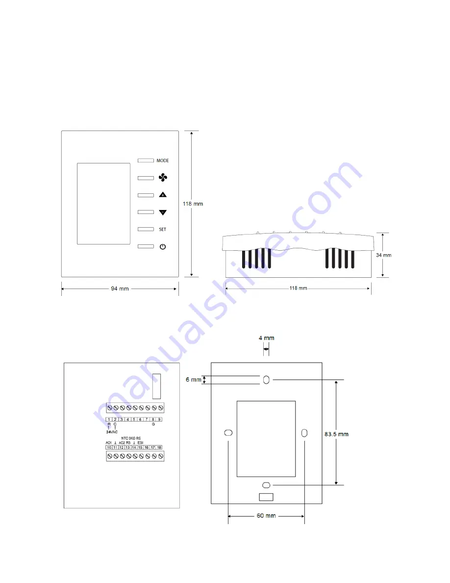
2.7
Mechanical (all dimensions are in mm)
Mounts directly onto wall, panel, standard 65×65mm junction box (hole pitch 60 mm) or
standard 2×4-inch vertical junction box (hole pitch 83.5mm).
Width: 94mm Height: 118mm Depth: 34mm
Страница 1: ...BAST 421C BW2 Wireless BACnet Communicating Thermostat for Modulating Fan Coil Operation BASstat Wireless Modulating Thermostat User Manual UM 15093500 AA1...
Страница 2: ...his publication may be reproduced transmitted transcribed stored in a retrieval system or translated into any language or computer language in any form or by any means electronic mechanical magnetic o...
Страница 3: ...6 Electromagnetic Compatibility 7 2 7 Mechanical all dimensions are in mm 8 3 Installation 9 3 1 Terminal Block Pin Assignments 9 3 2 Limited Power Source 9 3 3 Power Supply Precautions 10 3 4 Wiring...
Страница 4: ...ocally using the Engineering Menu or via a network connection to a BACnet client Contemporary Controls free BACnet Discovery Tool can be used for initial configuration of the thermostat over BACnet Co...
Страница 5: ...figurable control parameters such as deadband proportional gain integral rate and cycle time Adjustable minimum maximum set point ranges Three options for temperature reading o Built in temperature se...
Страница 6: ...UM 15093500 AA1 Page 5 1 2 Product Image and Main Features BASstat 421C B2 and BASstat 421C BW2...
Страница 7: ...re Sensor Provision for NTC Type 3k thermistor 2 2 Outputs Item Description Relay Output Fan Analog Outputs 0 10v modulating AO1 cooling AO2 heating Contact Rating SPST 2A at 30 VAC with inductive loa...
Страница 8: ...ard Test Method Description EN 61000 6 2 IEC 61000 4 2 Electrostatic Discharge Immunity EN 61000 6 2 IEC 61000 4 3 Radiated Radio Frequency Electromagnetic Field Immunity EN 61000 6 2 IEC 61000 4 4 El...
Страница 9: ...AA1 2 7 Mechanical all dimensions are in mm Mounts directly onto wall panel standard 65 65mm junction box hole pitch 60 mm or standard 2 4 inch vertical junction box hole pitch 83 5mm Width 94mm Heigh...
Страница 10: ...he remote sensor input RS is at terminals 13 and 14 The remote occupancy ESI input is a dry contact closure input located at terminals 14 and 15 Number Mark Comment Number Mark Comment 1 R 24 VAC high...
Страница 11: ...f wave devices have a common secondary connection called COMMON LO or GROUND Connect the HOT side of the secondary to the 24 VAC high side input on the BASstat and the LO side to 24 VAC common WARNING...
Страница 12: ...states to start stop the thermostat This will disable control ON OFF control can be accomplished over BACnet as well 2 At power ON press any button to start the User Mode operation Press the MODE but...
Страница 13: ...ACnet supervisor 3 Mode Select Select the working mode Cooling Heating or Ventilating After pressing the MODE button press the UP DOWN button to rotate the selections Dependent on Control Type 4 Fan A...
Страница 14: ...de automatic 4 Pipe Cooling or Heating with Manual Changeover In this control type the thermostat will wait for a command from user or BACnet supervisor to switch between Cool and Heat modes The user...
Страница 15: ...ulating cooling and heating with automatic changeover allows the thermostat to operate as fully stand alone Manual Changeover allows restrictionof mode selection to Cool only or Heat only where necess...
Страница 16: ...n Control Output Lowest Fan Speed is the speed the fan will default to after a control action Heating or Cooling with fan in AUTO mode If the lowest fan speed MSV4 is set as Stop 1 the fan will automa...
Страница 17: ...noccupied Cool and Unoccupied Heat setpoints AV8 9 When the state changes back to occupied the thermostat will return to the occupied set point values for Cooling and Heating Temperature Setpoint AV0...
Страница 18: ...UM 15093500 AA1 Page 17 to User mode Engineering Menu Flow Chart...
Страница 19: ...18 0 18 0 0 1 C F E10 Pb Proportional band or stage width 1 5 0 10 0 3 0 0 18 0 0 1 C F E11 diFF Stage differential 0 5 0 1 1 0 1 0 0 1 1 8 0 1 C F E12 LOC Bit Definition 0 MODE button dec 1 1 Down b...
Страница 20: ...display SP E18 door Door or Windows contact definition not applicable to all models 0 0 1 0 0 1 0 N O 1 N C E19 LFAn Lowest Fan speed in Auto fan mode 0 0 1 0 0 1 0 stop 1 low E20 Pct Output Percentag...
Страница 21: ...eedback not used E41 OPts Options not used E42 dlAb DI contact Defination not used E43 Hrt Communication Heartbeat Flip Flop 0 0 1 0 0 1 0 Off 1 On E44 CSPL Minimum Cooling Temperature Setpoint 18 0 0...
Страница 22: ...efaults Use Caution Press MODE to reset E65 End Exit Engineer Mode Menu Press MODE to exit engineering menu Note 1 Changing these values needs to unlock modification for communication parameters in ad...
Страница 23: ...stance Number must be configured prior to connecting to the BACnet IP network or BACnet communication will fail due to duplicate device instances Device instance can be modified in Engineering Menu it...
Страница 24: ...AP Passphrase to authenticate and connect to the AP ATTENTION Once connected to the Wi Fi access point the Wi Fi thermostat will use the Wi Fi access point credentials To ensure a secure connection w...
Страница 25: ...parties who know the SSID can connect to it This is configured in the Wi Fi router Store passwords in a safe place limit access to authorized parties only and provide instructions for password reset...
Страница 26: ...to Save New Settings and Restart or click Cancel to revisit IP configuration When OK is clicked a confirmation is displayed to indicate configuration is stored in the thermostat s EEPROM After reboot...
Страница 27: ...to use a different Wi Fi access point the thermostat must be reset and reconfigured There are 2 reset settings options for the Wi Fi thermostat Boot will restore Wi Fi communication parameters to def...
Страница 28: ...mostat and you will be prompted to confirm the restart Click OK to Save New Settings and Restart or click Cancel to revisit IP configuration When OK is clicked a confirmation is displayed to indicate...
Страница 29: ...Type Instance Readable Writable Description Range and Definition Current Temperature AI 0 R Current Temperature 999 9999 99 9 999 9 F Active Temperature Setpoint AI 1 R Active Temperature Set Point C...
Страница 30: ...te Temperature AI 15 R 3rd Remote Temperature Sensor Reading Value 999 9999 99 9 999 9 F Cooling Temperature Setpoint AV 0 R W Cooling Temperature Set Point C 0 500 0 0 50 0 F 320 1220 32 0 122 0 F Te...
Страница 31: ...180 18 0 18 0 F Proportional Band Stage Width AV 16 R W Proportional Band or Stage Width C 0 100 00 10 0 C F 0 180 00 18 0 F Stage Differential AV 17 R W Stage Differential C 1 10 0 1 1 0 C F 1 18 0 1...
Страница 32: ...W Minimum Output Voltage in Digital Value When Reach Low Limit for AO2 0 125 LSB Span Offset for AO2 AV 28 R W Span Offset for AO2 55 0 LSB Heartbeat Rate AV 29 R W Communication Heartbeat Minimum Ra...
Страница 33: ...Minimum Off Time AV 46 R W Minimum Off Time 0 600 seconds Minimum On Time AV 47 R W Minimum On Time 0 600 seconds Integral Cycle Time 2 AV 48 R W Integral Time and Output Cycle Time 2 0 500 Sec Set Po...
Страница 34: ...Off 1 On Smoke Fire Alarm Status BI21 R Smoke Fire Alarm Status 0 Off 1 On Status BI22 R Current Status 0 Off 1 On Valve Status BI23 R Valve Status 0 Off 1 On Alarm BI24 R Alarm Status 0 Off 1 On Fro...
Страница 35: ...Disable Enable Fan Output for Heating 0 Disable 1 Enable Heartbeat BV16 R W Communication Heartbeat Flip Flop 0 Off 1 On Fan Mode MSV 0 R W Fan Mode 1 Auto 2 Low 3 Med 4 Hi System Mode MSV 1 R W Work...
Страница 36: ...nty covers products only as delivered and does not cover repair of products that have been damaged by abuse accident disaster misuse or incorrect installation User modification may void the warranty i...
Страница 37: ...temporary Control Systems Inc Contemporary Controls Suzhou Co Ltd Contemporary Controls Ltd Contemporary Controls GmbH Tel 1 630 963 7070 Fax 1 630 963 0109 info ccontrols com Tel 86 512 68095866 Fax...