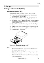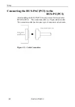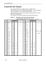
Major Parts of Each Component
FA-PAC(PCI)F13
10
CN4
:
Connect the power supply connector of the
ATX power supply. (Already connected)
CN5
:
Serves as the terminal for supplying power to
the power indicator LED on the PC casing
which contains the PC-MB14(PCI).
(Already connected)
CN6
:
Connector for the power switch.
(Already connected)
CN7
:
Connect the ATX power supply control cable.
(Already connected)
SLOT9
:
Slots available to the user. These slots are
one PCI bus level closer to the host than
SLOT1-SLOT8, SLOT10-SLOT13.
SLOT1-SLOT8, SLOT10-SLOT13
:
Slots available to the user. These slots are
one PCI bus level farther from the host than
SLOT9.
BUF SLOT
:
Dedicated to the BUS-PAC(PCI)
(BUS-PAC(PCI) already plugged). Do not
plug any other board in this slot.
LED1
:
+3.3VDC power indicator LED (Comes on
when the power supply is turned on.)
LED2
:
+5VDC power indicator LED (Comes on when
the power supply is turned on.)
LED3
:
+12VDC power indicator LED (Comes on
when the power supply is turned on.)
LED4
:
-12VDC power indicator LED (Comes on
when the power supply is turned on.)
Содержание BUS-PC(PCI)
Страница 1: ...FA PAC PCI F13 Long Size 13 Slots PCI Bus Chassis User s Guide ...
Страница 11: ...Introduction FA PAC PCI F13 6 ...
Страница 17: ...Major Parts of Each Component FA PAC PCI F13 12 ...
Страница 23: ...Setup FA PAC PCI F13 18 ...
Страница 33: ...A 46 172 LZN7031 021018 000321 ...


