background image

26

Select a place for mounting which is not shielded by, for example, reinfor-
ced concrete walls, steamed up mirrors, metal shelves etc. There should be
no devices with strong electrical fields such as mobile telephones, radios
and electrical motors etc. in the vicinity of device.
The above-mentioned points can disturb the radio transmission appreciab-
ly or limit the range. 

Mounting the radio camera

Caution!

Make sure before drilling or screwing in the screws that there are
no electric cables, pipes, cables or similar running through the
stonework or which could be damaged.

Fastening the wall bracket

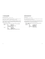
• Look for a suitable place for moun-

ting (possibly with a socket)

• Screw the wall bracket with the sup-

plied screws to a suitable wall or a
suitable platform use dowels if rele-
vant.

• Guide the tripod thread of the wall

bracket (10) into the thread hold of
the camera (3 or 7) and screw each
of them to one another.

• Align the camera and screw the late-

ral locking bolt tight.

The camera should not be directed directly to bright sunlight or to bright
lighting as this could overmodulate the picture.

27

Connecting the radio camera

• Connect the small voltage plug (9) of the power unit to the voltage supply jack of

the camera (4). 
Pay attention to the correct output voltage of 12 V DC!

• Insert the plug-in power unit into a suitable mains socket.
• The camera is now ready for use.

With the exception of the radio camera, the plug-in power unit is
not weather-proof. Pay attention before mounting the plug-in
power unit to a dry environment (for example. weather-proof hou-
sing or similar) 

Setting up the receiver

Set up the receiver in the vicinity of the surveillance monitor or TV set but not direct-
ly on the surveillance monitor. This could interfere with the transmission.

The most favourable location is approx. 1-2 m above the floor (better reception con-
ditions).

- there must be a mains socket in the vicinity of the reception location.

Connecting the radio receiver

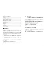
• Connect the AV cable as depicted to a sui-

table monitor or TV system with an AV
cinch input and the receiver (white/red
plug = audio (tone in mono), yellow plug =
video).

• Connect the small voltage plug of the

power unit (12) to the voltage supply jack
of the receiver (16). 
Pay attention to the correct output vol-
tage of 12 V DC!.

• Insert the plug-in power unit into a suitable

mains socket.

• The camera is now ready for use.

Monitor terminal

Содержание 75 06 82

Страница 1: ...rbehalten Reproduktionen jeder Art z B Fotokopie Mikroverfilmung oder die Erfassung in elektronischen Datenverarbei tungsanlagen bedürfen der schriftlichen Genehmigung des Herausgebers Nachdruck auch auszugsweise verboten Diese Bedienungsanleitung entspricht dem technischen Stand bei Drucklegung Änderung in Technik und Ausstattung vorbehalten Copyright 2004 by Conrad Electronic GmbH Printed in Ger...

Страница 2: ...nationalen Richtlinien Die CE Konformität wurde nachgewiesen die ent sprechenden Erklärungen sind beim Hersteller hinterlegt Bei Fragen wenden Sie sich an unsere Technische Beratung Deutschland Tel Nr 0180 5 31 21 11 Fax Nr 09604 40 88 48 e mail tkb conrad de Mo Fr 8 00 bis 18 00 Uhr Österreich Tel Nr 0 72 42 20 30 60 Fax Nr 0 72 42 20 30 66 e mail support conrad at Mo Do 8 00 bis 17 00 Uhr Fr 8 0...

Страница 3: ...g 10 Aufstellen und Anschließen der Geräte 10 Montage der Funkkamera 11 Anschluss der Funkkamera 12 Aufstellen des Empfängers 12 Anschluss des Funkempfängers 12 Inbetriebnahme 13 Wartung 15 Entsorgung 15 Behebung von Störungen 16 Technische Daten 17 Konformitätserklärung 18 Bestimmungsgemäßer Einsatz Der Verwendungsbereich des Funkkamerasystems umfasst die Objektüberwachung mit Bild und Ton Es die...

Страница 4: ... mit Niedervoltstecker An diesem Stecker liegt die Versorgungsspannung für die Funkkamera Beachten Sie die Ausgangsspannung von 9 V DC 10 Stativ Wandbefestigung mit Kugelgelenk Hier kann die Kamera mit dem Stativgewinde befestigt und beliebig ausgerichtet werden 47 Les réparations autres que celles qui ont été précédemment décrites doivent être uniquement exécutées par un technicien qualifié agréé...

Страница 5: ...onisation 7 Funkempfänger 11 Audio Video Verbindungskabel Klinkenstecker 11 auf Cinchstecker 11A Cinchkabel zur Verbindung des Empfängers mit dem Überwachungsmonitor Audio weiß oder rot Video gelb 12 Steckernetzgerät mit Niedervoltstecker An diesem Stecker liegt die Versorgungsspannung für die Funkkamera Beachten Sie die Ausgangsspannung von 12 V DC 13 Empfänger Antenne Die Antenne empfängt das vo...

Страница 6: ...Geräten durch geschultes Personal verantwortlich zu überwachen Beachten Sie auch die Sicherheitshinweise und Bedienungsanleitungen der übri gen Geräte die an das Gerät angeschlossen werden Wenden Sie sich an eine Fachkraft wenn Sie Zweifel über die Arbeitsweise die Sicherheit oder den Anschluss der Geräte haben 45 Changer le canal réglé sur la caméra sans fil et sur le récepteur commutateurs de ca...

Страница 7: ...einem Austausch von Teilen oder Baugruppen müssen die Geräte von allen Spannungsquellen getrennt sein wenn ein Öffnen der Geräte erforderlich ist Wenn eine Wartung oder Reparatur am geöffneten Gerät unter Spannung unvermeidlich ist darf das nur durch eine Fach kraft geschehen die mit den damit verbundenen Gefahren bzw den einschlägigen Vorschriften dafür vertraut ist Fassen Sie das Steckernetzteil...

Страница 8: ... befindet sich eine Netzsteckdose 43 Pour éviter toute distorsion ou désadaptation susceptibles d endommager l appareil brancher la fiche de raccordement audio blanche ou rouge uniquement sur une entrée Cinch audio Relier la fiche de raccordement vidéo jaune uniquement à une entrée Cinch vidéo En cas de doute quant au raccordement correct de l appareil contactez notre service d informations techni...

Страница 9: ... mentation 12 au connecteur d alimentati on du récepteur 16 Tenir compte de la valeur correcte de la tension de sortie de 12 V DC Enficher le bloc secteur dans la prise de courant appropriée Le moniteur est en ordre de marche Terminal du moniteur 11 Wählen Sie einen Montageort der nicht wie z B durch Stahlbetonwände bedampfte Spiegel Blechregale etc abgeschirmt wird In der Nähe des Senders bzw Emp...

Страница 10: ...s Empfängers 16 Achten Sie auf die korrekte Ausgangs spannung von 12 V DC Stecken Sie das Steckernetzgerät in eine geeignete Netzsteckdose Der Empfänger ist nun einsatzbereit 41 Choisir un emplacement de montage dénué de tout obstacle tel que murs en béton armé miroirs métallisés étagères en tôle etc Aucun appareil à fort champ électrique tels que par exemple les radiotéléphones les radios les mot...

Страница 11: ...et désiré Un emplacement approprié présente les propriétés suivantes si possible hermétique peu de vibrations bonne circulation d air présence d une prise de courant à proximité 13 Um Verzerrungen oder Fehlanpassungen zu vermeiden die zur Beschädigung des Gerätes führen können darf der Audio Anschlussstecker weiß oder rot nur mit einem Audio Cinchein gang verbunden werden Der Video Anschlussstecke...

Страница 12: ...ute interven tion de réglage de nettoyage de maintenance de mise en état ou avant tout rem placement de pièces ou de modules débrancher les appareils de toutes les sources de tension lorsqu il est nécessaire d ouvrir ceux ci Lorsque des opéra tions de maintenance ou de réparation sur l appareil ouvert et sous tension s avè rent inévitables celle ci doit uniquement être effectué par technicien spéc...

Страница 13: ...ns industrielles il convient d observer les consignes de préven tion des accidents relatives aux installations et moyens d exploitation électriques édictées par les syndicats professionnels Dans les écoles les centres de formation les ateliers de loisirs et de réinsertion la manipulation d appareils électriques doit être surveillée par un personnel respon sable spécialement formé à cet effet Tenir...

Страница 14: ...ble de connexion audio vidéo fiche jack 11 sur fiche Cinch 11A Câbles Cinch pour relier le récepteur au moniteur de surveillance audio blanc ou rouge vidéo jaune 2 Bloc d alimentation avec fiche basse tension Sur cette fiche se trouve la tension d alimentation pour la caméra sans fil Noter la tension de sortie de 12 V DC 3 Antenne réceptrice L antenne reçoit le signal envoyé par la caméra sans fil...

Страница 15: ...terrupteur à coulisse permet de régler trois canaux de transmission différents 9 Bloc d alimentation avec fiche basse tension Sur cette fiche se trouve la tension d alimentation pour la caméra sans fil Noter la tension de sortie de 9 V DC 10 Trépied fixation murale à l aide du joint à rotule Le filet du trépied permet de fixer et d orienter la caméra à volonté 17 Andere Reparaturen als zuvor besch...

Страница 16: ...s fil 42 Installation du récepteur 42 Raccordement du récepteur radioélectrique 42 Mise en service 43 Entretien 45 Elimination des éléments usés 45 Dépannage 46 Caractéristiques techniques 47 Déclaration de conformité 48 Utilisation conforme L utilisation de la caméra sans fil comprend la surveillance d objet assistée de l ima ge et du son Le système de caméra permet de surveiller et de protéger l...

Страница 17: ... Fax 0 892 896 002 du lundi au vendredi de 8h00 à 18h00 le samedi de 8h00 à 12h00 Suisse Tél 0848 80 12 88 Fax 0848 80 12 89 e mail support conrad ch du lundi au vendredi de 8h00 à 12h00 13h00 à 17h00 19 Introduction Dear Customer Thank you for purchasing this product Before starting operation read through these operating instructions completely observing all operating and safety instructions This...

Страница 18: ...roof camera is licensed for use outdoors The plug in supply unit must however be protected against dampness and wetness se weather proof housing or similar This radio camera system is not suitable for industrial use Any use other than that described above will lead to damage to this product and may in addition involve other risks such as for example short circuit fire electric shock 33 Radio range...

Страница 19: ...structions must be followed at all times Connection and operating elements fold out page Radio camera 1 Rain protection cover This covering can be pushed forwards or backwards 2 Camera lens 1 3 colour CMOS sensor with rigid lens 3 Fastening tripod thread For fastening the camera on the supplied tripod 10 4 Operating voltage jack Connecting jack for the low voltage plug 9 of the plug in power unit ...

Страница 20: ...ndition in terms of safety engineering To maintain this status and ensure safe operation the user must observe the safe ty instructions and warnings Caution and Note contained in these instruc tions for use 31 Eliminating disturbances By purchasing the active loudspeaker system you have acquired a product which has been designed to the state of the art and is operationally reliable However problem...

Страница 21: ...ions in these operating instructions which have to be observed at all times The plug in power unit is designed in compliance with protection class 2 The lightening symbol in a triangle warns against an electric shock or the impairment of the electrical safety of the device The hand symbol can be found when you are to be given tips and infor mation on operation Only for use in dry interior environm...

Страница 22: ...ndensation arising could destroy the device Allow the devices to reach room temperature before switching them on Electrical devices must be kept out of the reach of children Make sure that the device is sufficiently ventilated Avoid heavy mechanical stress high temperatures strong vibration or a excessive dampness which can damage devices Never place the device on an unstable surface If it fell ov...

Страница 23: ...e the channel switch into the desired channel position CH1 CH2 CH3 Close the protective covering again carefully water protection 25 This camera system creates uses and radiates high frequency energy If the devices cannot be installed and operated as stated in the instructions disturbance to other devices could be the result If the radio camera system should disturb oth er devices it is the duty o...

Страница 24: ...ture 27 Connecting the radio camera Connect the small voltage plug 9 of the power unit to the voltage supply jack of the camera 4 Pay attention to the correct output voltage of 12 V DC Insert the plug in power unit into a suitable mains socket The camera is now ready for use With the exception of the radio camera the plug in power unit is not weather proof Pay attention before mounting the plug in...

Отзывы: