Installation Manual
Connect
2
Car Anywhere GSM Kit
www.connect
2
car.com
18
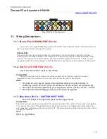
Figure 10 The 16 Pin Connector
11.
Wiring Descriptions
11.1.
Brown Wire GROUND WIRE (Pin16):
This wire (brown) supplies negative ground to the Device. This terminal must be connected properly in
order to prevent malfunctioning of the system.
Connection:
The pin-16 terminal from the device should be connected to the metal frame of the vehicle using an
existing machine threaded fastener. In the absence of already exiting machine threaded fastener, make
sure this terminal is in firm contact with a bright clean metallic surface of the vehicle. Partial contact
should be avoided as much as possible. Insufficient ground connection may affect operation of the device.
11.2.
Red Wire POWER WIRE (Pin15):
This is the main Power input to the device.
Connection:
The pin-15 terminal from the device should be connected to the battery’s positive terminal.
Remember to fuse this terminal with a 2A fuse. Avoid any moving part or hot surfaces.
HINT:
The positive wire can be found in the ignition harness of most vehicles. It
constantly reads +12V even when all accessories in the vehicle are switched off.
The unit can operate effectively from any power source 10.8 V...+32.0V
The unit also automatically powers up once power is applied.
11.3.
Blue Wire (Pin13) / IGNITION INPUT WIRE:
This wire (blue) is the ignition status monitoring terminal.
Connection:
The pin-13 terminal should be connected to the ignition terminal of the vehicle. This terminal is an ignition
“on” input to the device. Through this terminal the device receives a +12V signal when the ignition is on
and a negative ground signal when the ignition is off. The device monitors the ignition status of the vehicle
through this terminal.
Hint:
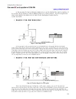
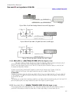
Refer to fig.4 below.


