Dual Port Mini PCIe GbE
Users Guide
Document: CTIM-00074
Revision: 0.00
Page 8 of 12
Date: 2021-11-03
INTERFACE PIN-OUTS
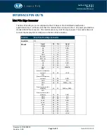
Mini PCIe Edge Connector
The Mini PCIe GbE pin-out is compliant to the PCI Express Mini Card Electromechanical
Specification Rev. 2.0. Please note that this module does not require the +1.5V power provided to a
standard Mini PCIe connector. This module uses only +3.3V for input power. This module does not
connect the Display Port or USB pins on the Mini PCIe connector.
Function
Mini PCIe Card Edge Connector
Location
P1
Pinout
Signal
Pin
Pin
Signal
WAKE#
1
2
+3.3V
NC
3
4
GND
NC
5
6
NC
NC
7
8
NC
GND
9
10
NC
REFCLK-
11
12
NC
13
14
NC
GND
15
16
NC
NC
17
18
GND
NC
19
20
NC
GND
21
22
PEREST#
PER-
(from this module to
system)
23
24
+3.3V
PER+
(from this module to
system)
25
26
GND
GND
27
28
NC
GND
29
30
SMBus_CLK
PET-
(from system to this
module)
31
32
SMBus_DATA
PET+
(from system to this
module)
33
34
GND
GND
35
36
NC
GND
37
38
NC
+3.3V
39
40
GND
+3.3V
41
42
NC
GND
43
44
NC
NC
45
46
NC
NC
47
48
NC
NC
49
50
GND
NC
51
52
+3.3V


