EN
30
OPO 5342N
EN
27
OPO5342
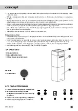
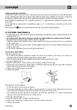
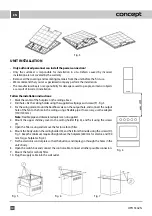
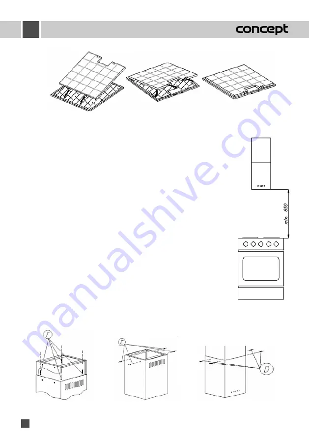
Fig. 3
Fig. 5
Fig. 6
Fig. 7
UNIT INSTALLATION
•
Only authorized personnel can install the power connection!
• Only the customer is responsible for installation in situ. Defects caused by incorrect
installation are not covered by the warranty.
• Remove all the covering and marketing materials from the unit before the first use.
• We recommend that you let a specialized company perform the installation.
• The manufacturer bears no responsibility for damage caused to people, animals or objects
as a result of incorrect installation.
Follow the installation instructions:
1. Mark the center of the hotplate on the ceiling above.
2. Drill holes. Fix the ceiling holder using the supplied wall plugs and screws (F) - Fig. 5.
3. For the airing mode, mount the backflow valve on the output hole, and connect the output
hole of the fan to the hole in the ceiling using a flexible pipe. If necessary, use the adapter
(150/120 mm).
Note:
Flexible pipe and diameter adapter are not supplied.
4. Mount the upper chimney cover to the ceiling holder (Fig. 6), and fix it using the screws
(F).
5. Open the filter casing and remove the fat (or carbon) filter.
6. Mount the body unit on the ceiling holder (A), and fix it from the inside using the screws (D),
Fig. 7. Keep the minimum required height above the hotplate (650 mm for electric, and 700
mm for gas hotplates, Fig. 4).
7. Fix the electronic control plate so that the buttons and display go through the holes in the
unit‘s body.
8. Open the switch box and connect the control cable. Connect all other possible connectors.
9. Mount the fat (or carbon) filter.
10. Plug the supply cable into the wall outlet.
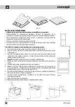
Fig. 4

