CONCEPT
CONCEPT
CONCEPT
CONCEPT
CONCEPT. Small Low Profile P
. Small Low Profile P
. Small Low Profile P
. Small Low Profile P
. Small Low Profile Powered Enclosure.
owered Enclosure.
owered Enclosure.
owered Enclosure.
owered Enclosure.
Installation Notes.
2
Installing the Small Low Profile Powered Enclosure.
Electrical AC Mains Power connection.
In countries where the module is supplied without a mains power cord, a suitable mains power cord for connection to the 240V
AC Mains supply must be installed by a suitably qualified electrician or technician.
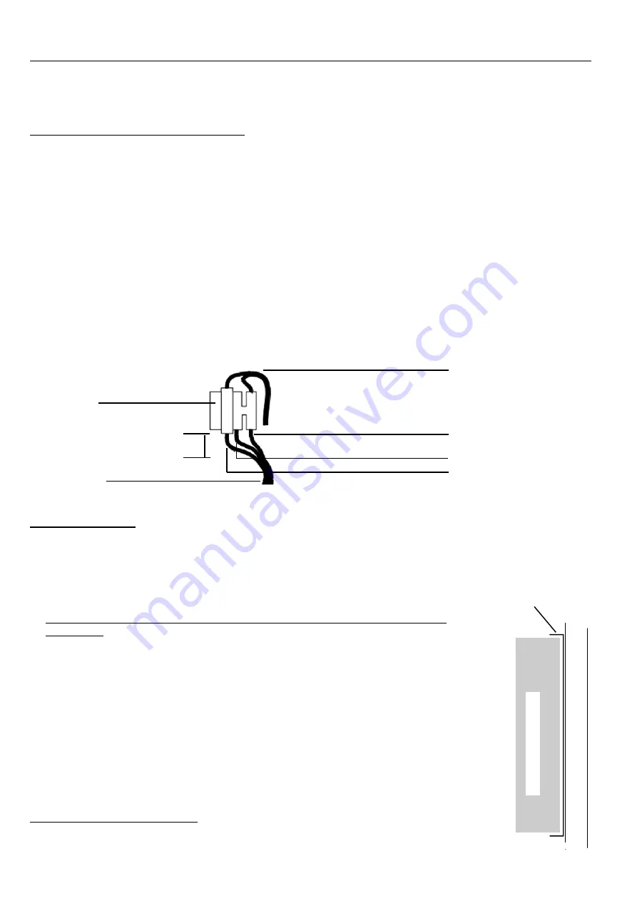
1. Strip 30mm of the sheath from the end of the power cord. Trim 5mm from the ends of the Active and Neutral conductors so
that the Earth conductor remains slightly longer.
2. Strip 5mm of insulation from each of the conductors and feed at least 100mm of the power cord through the AC mains cable
entry hole in the bottom of the chassis.
3. Terminate the power cord in the terminal and fuse block as illustrated in Diagram 1 below. Note that the Active wire is
always connected into the termination nearest to the fuse.
4. Determine the appropriate length of power cord between the terminal block and the cable entry hole. (Approx. 100mm)
Working from the bottom of the chassis, fit the plastic grommet (supplied) around the power cord and apply pressure to both
sides of the grommet to clamp the cable. The grommet can now be inserted into the AC mains cable entry hole.
IMPORTANT NOTE: An AC Mains socket-outlet shall be installed near the equipment and shall be easily accessible for
connection of the mains power cord.
Transformer
input connection.
Neutral
Earth
Live (Active)
Diagram 1.
25mm
Mounting the Unit. See Diagram 3 on the following page.
1. Installation environment should be maintained at 0º to 40º Celsius and 15% to 85% Relative
humidity (non-condensing)
2. The enclosure must be secured to a flat, vertical surface using fasteners through the four
“keyhole” mounting holes in the chassis. We recommend mounting the enclosure with the
Mains Cable entry and Transformer at the bottom as shown in Diagram 3.
3. When mounting this product onto flammable surfaces, a fire protection backplate MUST BE
INSTALLED.
(See Diagram 2)
Any Conduit entry points that have had the knockout
removed but will not be used, must also be resealed using 25mm Conduit Plugs.
4. Fit the tamper switch into the tamper switch bracket. Install this assembly by placing the
tamper switch plunger in the hole provided in the base, and the tongue on the bracket through
the slot provided in the lip in the top of the chassis.
5. The Battery is normally installed in the bottom of the enclosure.
(See Diagram 3)
An
optional Battery retaining bracket (Part Number: 926005) can be used if the enclosure is not
mounted as recommended in Step 2.
6. The metal chassis is electrically earthed and the Circuit Board Assembly is electrically
isolated from the chassis. When mounting and wiring the Module, the Installer must ensure
that this isolation is maintained.
Connecting Power to the PCB. See Diagram 3.
1. The connection between the AC mains transformer output (A) and the “AC” Input
connections on the PCB (B) is pre-wired in the factory.
Fuse. 1.0 Amp
Slow Blow
M205 (20mm)
AC Mains cable.
1234
1234
1234
1234
1234
1234
1234
1234
1234
1234
1234
1234
1234
1234
1234
1234
1234
1234
1234
1234
1234
1234
1234
1234
1234
1234
1234
1234
1234
1234
1234
1234
1234
1234
1234
1234
1234
1234
1234
1234
1234
Flammable Mounting Surface.
Diagram 2.
Refer to “Mounting the
Unit”, Step 3.
Fire Protection
Backplate.
Equipment Enclosure.


