background image

- 7 -

thermostats, the zone valves/pumps, the boiler and the power supply are 

accessible.

• 

Select the location of the zone controller near the boiler and/or the manifold 

and create the holes on the wall for installation.

• 

Secure the zone controller board to the wall using the supplied screws.

• 

Connect the wires of the needed heating equipment (the wires of the 

thermostats, the zone valves/pumps and the boiler) and the wires for 

power supply as shown in the figure below.

• 

Replace the front cover of the device and secure it with the screws at the 

bottom of the cover.

• 

Connect the zone controller to the 230 V mains network.

connection points of the thermostats

connection points for power supply

fix phase 

(working when 

the power switch 

is turned on)

fuse (15 A)

connection points controlling the boiler

connection points of the heating zones

In case of using electro-thermal zone valves that operate slowly and all the 

zones are closed when the boiler is inactive, then the boiler should be started 

with a delay in order to protect the pump of the boiler. In case of using electro-

thermal zone valves that operate fast and all the zones are closed when the 

boiler is inactive, then the valves should close with a delay in order to protect the 

pump of the boiler. See Section 

for more information on the delay funcions.

5. DELAY OF THE OUTPUTS

When designing the heating zones - in order to protect the pumps - it is advisable 

to keep at least one heating circuit that is not closed by a zone valve (e.g. bathroom 

Содержание Q4Z

Страница 1: ...Operating Instructions zone controller for controlling 1 to 4 heating zones COMPUTHERM Q4Z...

Страница 2: ......

Страница 3: ...h other or in case of need all zones can operate at the same time To control more than 4 zones at a time we recommend using 2 or more COMPUTHERM Q4Z zone controllers 1 zone controller needed per 4 zon...

Страница 4: ...connection points T1 T2 T3 T4 one for a room thermostat and one for a zone valve pump Z1 Z2 Z3 Z4 The thermostat of the 1st zone T1 controls the zone valve pump of the 1st zone Z1 the thermostat of t...

Страница 5: ...reover the four heating zones also have a joint connection point for a zone valve pump Z1 4 If any of the four thermostats T1 T2 T3 and or T4 switches on then beside the 230 V AC voltage appearing at...

Страница 6: ...aratus to be connected to it is connected to the 230 V mains voltage Modifying the device can cause electric shock or product failure Attention We recommend that you design the heating system you want...

Страница 7: ...ats connection points for power supply fix phase working when the power switch is turned on fuse 15 A connection points controlling the boiler connection points of the heating zones In case of using e...

Страница 8: ...lashes with 3 second intervals the LED stops flashing and indicates the current operating mode Automatic Manual Then the working mode can be changed by pressing the A M button again After 10 seconds t...

Страница 9: ...of the thermostats the zone valves pumps associated with the thermostat open start and the boiler also starts also taking the Turn on delay function into account see Section 5 By pressing the A M AUTO...

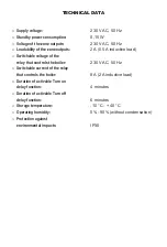
Страница 10: ...tchable voltage of the relay that controls the boiler 230 V AC 50 Hz Switchable current of the relay that controls the boiler 8 A 2 A inductive load Duration of activable Turn on delay function 4 minu...

Страница 11: ......

Страница 12: ...ves EMC 2014 30 EU LVD 2014 35 EU and RoHS 2011 65 EU Copyright 2020 Quantrax Ltd All rights reserved Manufacturer QUANTRAX Ltd H 6726 Szeged F lem le u 34 Hungary Telefon 36 62 424 133 Fax 36 62 424...

Отзывы: