background image

v1.0 


[email protected] 


www.compressedairalliance.com  

11 

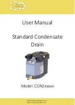
 Standard Condensate Drain 


User Manual v1 

Step 1.5 

 Connect power 

Unscrew the connector screw and remove the cap from the connector to connect your power cable as 
illustrated in Figure 1.5 below.  

Replace the power connector, tighten the connector screw (max. torque 0,3 Nm) and turn on the power 
supply. 

Make sure the gasket is secured properly to ensure IP65 rating.  

Step 1.6 

 Open ball valve 

Slowly open the ball valve to restore normal system pressure. 

The drain is now under pressure! 

Step 1.7 

 Test the drain 

Press and hold down the TEST button to check the valve function. 

A purging sound must be heard.  

Step 1.8 

 Your condensate drain is now ready. 


Содержание CON2 Series

Страница 1: ...sales compressedairalliance com www compressedairalliance com 1 User Manual Standard Condensate Drain Model CON2xxxxx ...

Страница 2: ...iance com 2 Standard Condensate Drain User Manual v1 Table of Contents Notices 3 About Condensate Drains 4 Specifications 6 Condensate Drain Pack 8 Installation 9 Alarm 12 Maintenance and Cleaning 14 Warranty 17 Need help 17 Installation and Service Record 18 ...

Страница 3: ...consequences caused thereby Safety and Warnings Ignoring the warnings can lead to serious injury and or cause damage When handling operating or carrying out maintenance on this product personnel must employ safe working practices and observe all local health safety requirements and regulations Improper operation or maintenance of this product could be dangerous and result in an accident causing da...

Страница 4: ...emove condensate at critical points on the supply side of the system As these operate on a set timer they are adjusted for the worst case scenario and never looked at again unless there is a moisture event downstream Valuable compressed air is dumped every time these types of drains operate resulting in increased operating costs and losses in system efficiency Zero loss drains are far more effecti...

Страница 5: ...ngs are constructed from robust coated aluminum and not from plastic This ensures that no damage is occurring during transport installation functional operation and the subsequent maintenance moments throughout the drain s working life High grade coil insulation protect the copper wire from overheating and top brand PCB components are applied on our electronic modules The FPM seals have been speci...

Страница 6: ...2 BSP Inlet Height Top 110 mm Side 75 mm 15 mm Top 4 3 Side 3 0 0 6 Outlet Connection 1 4 BSP Outlet Height 15 mm 0 6 Power Power Supply Voltage 230VAC or 24VDC Connectors DIN 43650 B Alarm Alarm feature type Contact output switch voltage free available in two versions A3 U3 and A4 U4 A3 U3 Normally open contacts closed when in alarm phase LED on the drain is OFF when in operation and ON when in a...

Страница 7: ...liance com 7 Standard Condensate Drain User Manual v1 Installation Type Permanent or temporary installation Maintenance Frequency Annually Warranty Period 12 Months Dimensions Parts List 179 mm 7 0 87 mm 3 4 114 mm 4 5 112 mm 4 4 77 mm 3 0 8 mm 0 3 14 mm 0 6 ...

Страница 8: ... Drain Optional Accessories The following accessories are available for the flow meter Talk to your local dealer or Compressed Air Alliance or pricing and other accessories M12 connectors Male female and Y type Data Acquisition and Analysis software Data Cables Instruction manual Available on the Compressed Air Alliance website www compressedairalliance com products Standard Condensate Drain ...

Страница 9: ...eally at a downwards slope 1 Avoid water pockets when installing the feed pipe this will create an air lock If the downwards slope of the feed pipe is not sufficient or if any other flow problem occurs a venting line must be installed to prevent an air lock We advise to apply a 1 2 pipe diameter and 1 2 elbows to avoid an air lock Do not narrow the feed pipe when installing additional adapters or ...

Страница 10: ...ate a suitable condensate draining point in your compressed air system and connect your drain as illustrated in Figure 1 3a below The use of a ball valve is advisable Outlet connection Connect the outlet to a condensate cleaner refer to Figure 1 3b below We advise to use the nipple supplied with your drain If it is necessary to use an alternative nipple make sure it is of the correct thread 1 4 BS...

Страница 11: ...1 5 below Replace the power connector tighten the connector screw max torque 0 3 Nm and turn on the power supply Make sure the gasket is secured properly to ensure IP65 rating Step 1 6 Open ball valve Slowly open the ball valve to restore normal system pressure The drain is now under pressure Step 1 7 Test the drain Press and hold down the TEST button to check the valve function A purging sound mu...

Страница 12: ... valve inside the drain indicating a service interval is required If the alarm has been activated the drain will open for two times and run a diagnostic cycle see section 2 in the diagram below After the alarm cycle the alarm will be deactivated automatically and the drain will return to its normal operation If the reason for the alarm has not been solved the drain will repeat the alarm cycle Opti...

Страница 13: ...m panel 3 Connect your alarm device to a power supply The alarm switch type is a contact output switch An external power supply is required as the alarm connection point on the drain works like a relay switch only 4 Connect the power supply to the drain alarm connector to close the circle Replace the connector and tighten the connector screw Max torque 0 3Nm Make sure the gasket is secured properl...

Страница 14: ...anceto purchase the service kit Maintenance instructions are provided with the kit Cleaning Instructions WARNING Depressurise the system before installation or maintenance is carried out Note These instructions are for cleaning the drain If your drain requires maintenance i e replacement of wearing components please contact Compressed Air Alliance for maintenance instructions Tools required to cle...

Страница 15: ...g the four housing bolts using a 5mm Allen key and remove the top part from the reservoir Step 5 Slide the electronics compartment up and unscrew the valve from the bottom part of the housing using a 23mm wrench WARNING make sure the electronics compartment does not get wet this will damage the unit Step 6 Clean all valve parts thoroughly Make sure there s no debris left in the other parts of the ...

Страница 16: ...cs have not been in contact with water WARNING make sure the cable connected to the electronics compartment does not get damaged while re assembling the components Step 10 Replace the power connector tighten the connector screw max torque 0 3 Nm and turn on the power supply Make sure the gasket is secured properly to ensure IP65 rating Make sure the display lights up to check if the power supply i...

Страница 17: ...there is a charge for other services such as labour to remove or reinstall the instrument transport and packing Warranty repairs do not extend the period of warranty The following damage is excluded from this warranty Improper use and non adherence to the user manual Use of unsuitable accessories External influences e g damage caused by vibration damage during transportation excess heat or moistur...

Страница 18: ...eg CON200001 Serial Number Installed by Installed On date Service Record We advise to check this product at least once a year and replace serviceable parts when necessary Clean the strainer periodically to avoid possible blocking causes by rust and or debris Check the valve function periodically by pressing the TEST button A purging sound must be heard Date Description Name ...

Страница 19: ...edairalliance com www compressedairalliance com 19 Standard Condensate Drain User Manual v1 Compressed Air Alliance Phone Australia 1300 558 526 E mail sales compressedairalliance com Website www compressedairalliance com ...

Отзывы: