5
Using the HT-PR Dielectric Withstand Tester
The dielectric withstand test involves high voltage and caution should be exercised when using
the tester. The return lead of the tester is connected to ground potential and when properly
connected to the equipment being tested, it will guard against the operator contacting high
voltage. Always make sure the return lead is firmly connected to exposed dead metal before start
testing. To make sure if the connections between the dielectric withstand tester and the
equipment under test is correct, see the connection section for more detail. In the sections below,
the three tests are explained.
Ground Check
The Ground check ensures that the grounding pin of the power supply cord is properly connected
to the exposed dead metal of the chassis. If this connection is absent, the exposed dead metal of
your product could be at line potential indefinitely after an internal wiring fault, causing risk of
shock to anyone touching it.
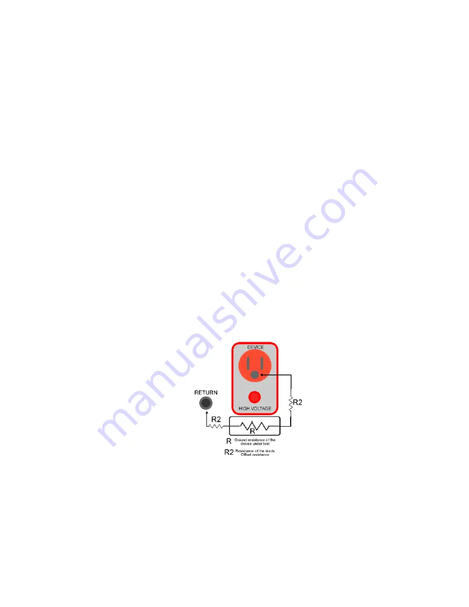
To make sure that the measure of the ground resistance is correct, the Offset resistance feature is
available in the HT-PR series, this ensures that the resistance of the cables doesn’t affect the
device ground resistance measurement.
This setting indicates the limit of the ground connection resistance value from 0.01 to 1.50
Ω
, for
the ground continuity test, the measured resistance must not exceed 2.00
Ω
(including the
resistance of the cables), otherwise the HT-PR will put an open ground result, in this test three
different values of resistance are involved, the measured resistance (continuously checked by the
HT-PR), the Resistance of the cables (offset resistance) and the resistance setting, the following
figure shows the different resistances involved in this test.
Figure 2. Device connection, resistances involved in a ground test.
Содержание HT-2000PR
Страница 2: ......
Страница 4: ...ii...
Страница 6: ...iv Voltage Calibration Adjustment 33 Current Calibration Adjustment 34 Ground Resistance adjustment 35...
Страница 7: ...1...
Страница 20: ...14 Figure 3 Controls Indicators Connectors Model HT 3000PR Front Panel...
Страница 22: ...16 Figure 4 Controls Indicators Connectors HT PR Rear Panel...


