


3-22
RAID Array 3000 Controller Shelf Hardware User’s Guide
Compaq Confidential – Need to Know Required
Writer: Bob Young Project: RAID Array 3000 Controller Shelf Hardware User’s Guide Comments:
Part Number: EK-SMCPQ-UG. D01 File Name: d-ch3 Installation and Maintenance.doc Last Saved On: 12/4/00 1:08 PM
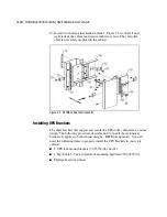
Cabling a Four Device Expansion Shelf Subsystem
1.
Ensure the physical installation phase of installing and securing shelf
brackets and shelves (including the UPS) has been accomplished and
that the shelves are secured within the shelf bracket the shelf lock
provided.
2.
Remove the device I/O module from the controller shelf and ensure the
switch positions of SCSI bus termination switch S4 are set as shown in
Figure 3– 9. Replace the module in the controller shelf.
3.
Remove the personality I/O module from device expansion shelf # 1 and
set SCSI bus termination switch S4 and SCSI bus address switch S3 on
this module as shown in Figure 3-13.
4.
Remove the personality I/O modules from device expansion
shelves # 2, # 3, and # 4 and repeat step 3.
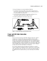
5.
Connect the black AC power cords (supplied with the shelves) from the
primary AC power source to the outside power supply on each shelf
(see Figure 3-10).
6.
Connect the gray power cables from the inside power supply on each
shelf to the power receptacles on the back of the UPS (ensure the UPS is
connected to a secondary AC source.
7.
Connect the single-connector end of a Trilink adapter to the SCSI
connector on the personality module in device expansion shelf # 1.
Tighten the screws on the adapter to ensure it is firmly seated.
8.
Connect the single-connector end of a second Trilink adapter to the
SCSI connector on the personality module in device expansion
shelf # 2. Tighten the screws on the adapter to ensure it is firmly seated.
9.
Connect a 0.5-meter SCSI cable (BN37A-0E) from one connector on the
adapter connected to shelf # 1 to the top SCSI connector (device bus 1)
on the front of the Controller shelf device I/O module.
10.
Connect a second 0.5-meter SCSI cable (BN37A-0E) from the other
connector on the adapter connected to shelf # 1 to the SCSI connector
on the front of the personality I/O module on the device expansion
shelf # 3.
11.
Connect a third 0.5-meter SCSI cable (BN37A-0E) from the one
connector on the adapter connected to shelf # 2 to the bottom SCSI
connector (device bus 0) on the front of the controller shelf device I/O
module.