Compaq Presario SR5900 - Desktop PC Скачать руководство пользователя страница 8

6

517212-001

— Removing and Replacing the Hard Disk Drive

15

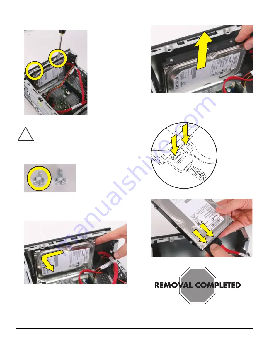
Remove the two hard drive retention screws. Set them 
aside for use with the new hard drive.

16

Slide the hard drive to the rear of the computer until it 
stops. Then slide the hard drive toward the center of 
the computer to release it.

17

Lift the hard drive straight up and out.

18

Press the release button on the end of the power cable 
and the data cable while disconnecting these cables 
from the drive.

CAUTION: 

Using retention screws that are 

too long can damage some hard disk 
drives. The hard disk drive retention screws 
are slightly shorter than the rest of the 
screws. Set these screws aside for use with 
the replacement hard disk drive.

Содержание Presario SR5900 - Desktop PC

Страница 1: ...Printed in Upgrading and Servicing Guide...

Страница 2: ......

Страница 3: ...Removing and Replacing the Hard Disk Drive Features may vary by model...

Страница 4: ......

Страница 5: ...is extremely sensitive to shock impact Do not bang or drop it Do not touch the circuit board Static electricity can damage the drive CAUTION This product contains components that are easily damaged b...

Страница 6: ...e power from the wall and from the back of the computer 4 Turn off all peripheral devices such as monitor printer and external drives and disconnect them from the computer 5 Disconnect the mouse keybo...

Страница 7: ...drive cage to the front of the computer 12 Lift the front edge of the optical drive and cage assembly 1 and then slide the tabs 2 out of the notches at the rear of the computer 13 Disconnect the powe...

Страница 8: ...d the center of the computer to release it 17 Lift the hard drive straight up and out 18 Press the release button on the end of the power cable and the data cable while disconnecting these cables from...

Страница 9: ...t when properly installed 3 Reconnect the power cable and the data cable to back of the hard drive IMPORTANT The new replacement part may not look the same as the original part due to different manufa...

Страница 10: ...to the bay and then to the right until it locks When the drive is properly located the threaded holes in the drive line up with the holes in the drive bay and the power and data cables will route prop...

Страница 11: ...slots at the rear of the computer Then lower the front of the drive and cage assembly onto the computer 9 Replace the two optical drive cage screws 10 Stand the computer upright 11 Insert the tabs on...

Страница 12: ...rd Disk Drive 13 Align the tabs on the inside edge of the left side panel with the slots in the edge of the left side of the computer case 14 Slide the left side panel into place 15 Replace the screws...

Страница 13: ...517212 001 Removing and Replacing the Hard Disk Drive 11...

Страница 14: ...12 517212 001 Removing and Replacing the Hard Disk Drive...

Страница 15: ...Removing and Replacing the Optical Disc Drive Features may vary by model...

Страница 16: ......

Страница 17: ...optical disc drive with care It is easy to damage It is sensitive to shock impact Do not bang or drop it CAUTION This product contains components that are easily damaged by electrostatic discharge ES...

Страница 18: ...the power from the wall and from the back of the computer 4 Turn off all peripheral devices such as monitor printer and external drives and disconnect them from the computer 5 Disconnect the keyboard...

Страница 19: ...11 Remove the two screws that secure the optical drive cage to the front of the computer 12 Lift the front edge of the optical drive and cage assembly 1 and then slide the tabs 2 out of the notches at...

Страница 20: ...oles marked 2 on the drive cage with the holes on the sides of the disc drive NOTE The black optical drive cage retention screws are metric screws IMPORTANT The new replacement part may not look the s...

Страница 21: ...and cage assembly into the slots at the rear of the computer Then lower the front of the drive and cage assembly onto the computer 6 Replace the two optical drive cage screws 7 Stand the computer upri...

Страница 22: ...the left side of the bezel in place 10 Align the tabs on the inside edge of the left side panel with the slots in the edge of the left side of the computer case 11 Slide the left side panel into plac...

Страница 23: ......

Страница 24: ......

Страница 25: ......

Страница 26: ...Copyright 2009 Hewlett Packard Development Company L P The information contained herein is subject to change without notice Version 2 0...

Отзывы: