


United States December 12, 2002
Maintenance and Service Guide
Compaq Presario 5400 Series Computers
Troubleshooting
without
diagnostics
TROUBLESHOOTING
Troubleshooting Without Diagnostics
This section describes some simple, preliminary tests and guidelines for troubleshooting the
computer.
Checklist For Solving Minor Problems
If you encounter some minor problem with the computer or software application,
go through the following checklist for possible solutions before running any of the diagnostic utilities:
■
Is the computer connected to a working power outlet?
■
Is the computer turned on and the power light illuminated?
■
Are all cables connected properly and seated?
■
Are all of the necessary device drivers installed?
■
Is the
CONFIG.SYS
file correct?
■
Is the
AUTOEXEC.BAT
file (MS-DOS) or
STARTUP.CMD
file correct?
■
Was a nonbootable diskette loaded in the diskette drive at power-up?
■
Are all switch settings correct?
■
Was Computer Setup run after installing options (memory, disk drives, etc.) and
before installing industry standard architecture boards?
Quick checks and possible solutions for problems related to these topics:
are provided in the tables below. The procedure for
is also described.
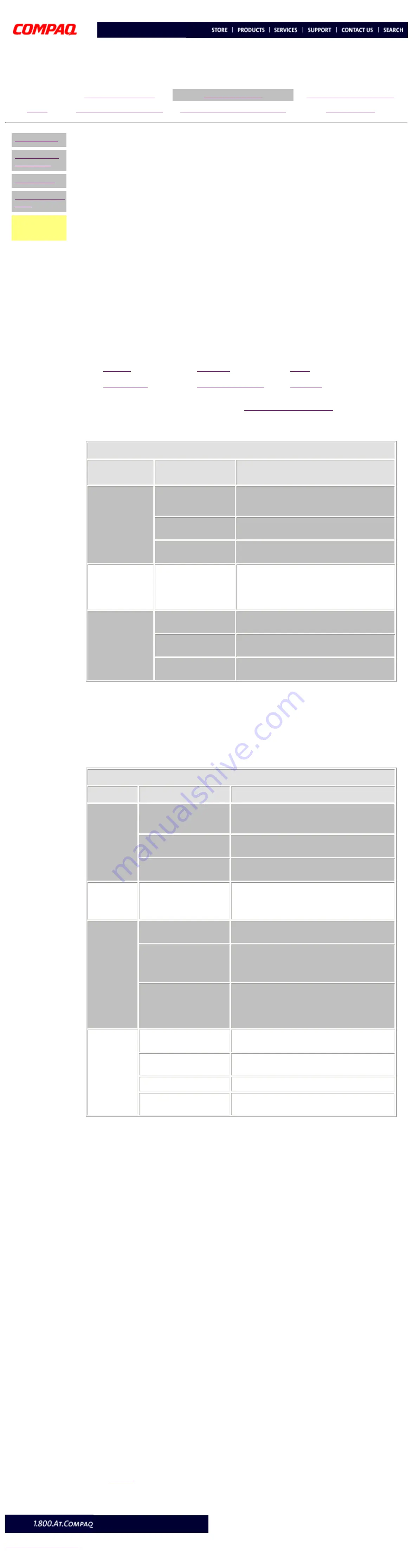
CD drive
Problem
Probable
cause(s)
Possible solution
Cannot read
compact disc.
CD is not properly
seated in the drive.
Eject the CD, then re-insert it, pressing down
on the CD firmly to correctly seat it in the
drive.
CD has been loaded
upside down.
Eject the CD, turn it over, then reload.
CD may be dirty or
scratched.
Clean the CD or load another CD.
Cannot eject
compact disc
(tray-load
only).
CD is not properly
seated in the drive.
Turn off the computer, insert a straightened
paper clip into the emergency eject hole, then
push firmly. Slowly pull the tray out from the
drive until the tray is fully extended, then
remove the CD.
CD drive devices
are not
detected.
Power cycle delay.
After turning the computer off, wait 30
seconds before turning the computer on again.
CD drive is not
connected properly.
Open the computer and check to see that the
drive cable is connected properly.
Proper driver is not
loaded
Restart the system and make sure the CD
drive drivers are loaded.
DVD drive
Problem
Probable cause(s)
Possible solution
Cannot
read DVD
disk
DVD or CD is not properly
seated in the drive.
Eject the DVD or CD, press down on the DVD or
CD firmly to correctly seat it in the drive, then
reload.
DVD or CD has been
loaded upside down.
Eject the disk, turn it over, then reload.
DVD or CD disk may be
dirty or scratched.
Load another DVD disk.
DVD does
not work in
the DOS
mode.
Proper drivers are not
loaded.
Restart the system and make sure the DVD
drive drivers are loaded.
Cannot
eject DVD
disk.
The system is in the
Sleep mode.
Press the Power button to bring the system back
to full power, then eject the DVD.
The DVD, diskette, or
hard drive was active
when attempting to eject
the DVD.
Wait until all drive activity ends (the CD/hard
drive light and diskette drive light will go out),
then try to eject the DVD.
DVD disk is not properly
seated in the drive.
Turn off the computer, insert a straightened
paper clip into the emergency eject hole, then
push firmly. Slowly pull the tray out from the
drive until the tray is fully extended, then
remove the DVD disk.
DVD drive
devices are
not
detected.
DVD drive is not
connected properly.
Open the computer and check to see that the
drive cable is connected properly.
Incorrect driver is
installed.
Ensure the correct driver is installed in
CONFIG.SYS.
Drive has been changed.
Make sure the jumper setting is set for "Slave."
Proper drivers are not
loaded.
Restart the system and make sure the DVD
drive drivers are loaded.
Resolving Hardware Conflicts
Hardware conflicts occur when two or more peripheral devices attempt to use the same hardware
resources. I/O addresses, interrupts, and DMA channels are the most common hardware resources
used by peripheral devices. For example, the factory default settings for the MIDI port audio interface
are:
Base I/O address
220H
MIDI Port Base I/O address
330H
Interrupt
IRQ 5
8-bit DMA
Channel 1
When different peripheral devices use the same hardware resources at the same time, the devices
and/or the system may not function properly. You can resolve hardware conflicts by ensuring that no
devices are configured to use the same hardware resources. These resources can either be dipswitch
or jumper settings on the peripheral card or software configurable resources. The Computer Setup
selection of your Compaq Utilities allows you to view and modify the settings for the peripheral
devices factory installed in your system. Refer to the
User's Guide
for the particular peripheral cards
you wish to install for information on how to view and select their settings.
To resolve hardware conflicts:
1 Change the hardware settings of your audio card or other peripheral card in your
system if the peripheral card is using any settings used by the factory-installed
devices.
2 If you are unsure of the settings of the peripheral cards, you can isolate the
source of the problem by temporarily removing all cards not manufactured by
Compaq, or resetting the default settings and running Compaq Utilities. After
that, add the cards back one at a time until the card that is causing the conflict is
found.


