Compaq Presario 5070 Скачать руководство пользователя страница 23

Compaq.com - Compaq Presario Maintenance and Service Guide - 5200 Series

United States     December 10, 2002 


Maintenance and Service Guide

Compaq Presario 5000, 5100, and 5200 Series Computers

MSG index

Product Description

Troubleshooting

Illustrated Parts Catalog

Home

Removal & Replacement

Jumper & Switch Information

Specifications

Clearing CMOS

Power-On Self 
Test (POST)

Configuration

Diagnostic error 
codes

Troubleshooting 

without 

diagnostics

l


TROUBLESHOOTING

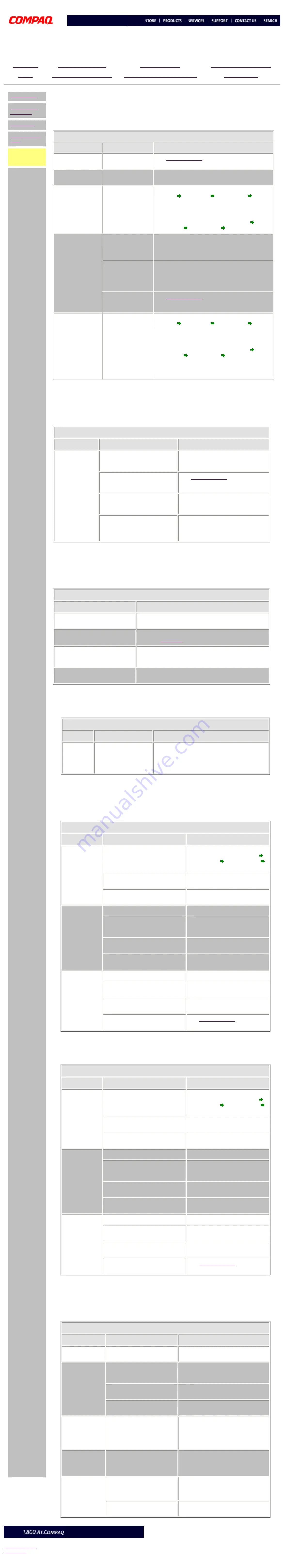
Troubleshooting Without Diagnostics (continued)


Hard drive

Problem

Probable cause(s)

Possible solution

Hard drive error 

occurs.

Hard disk has bad 

sectors or has failed. 

Run 

Computer Setup

Reformat the hard disk.

Drive not found.

Cable could be 

loose. 

Check cable connections.

Disk transaction 

problem.

Either the directory 

structure is bad or 

there is a problem 

with a file. 


From the desktop click on the 

Start

 menu. Choose 

Program   Accessories   System Tools   

Scandisk 

to check for problems. If problems exist, 

run Scandisk and checkmark the "Automatically fix 

errors" box at the bottom to correct the problems. 

If a large number of lost allocation units is found, 
click on the 

Start

 menu. Choose 

Program   

Accessories   System Tools   Disk Defragmenter

Nonsystem disk 

message.

The system is trying 

to start from a 

diskette that is not 

bootable. 

Remove the diskette from the diskette drive.

The system is trying 

to start from the 

hard drive but the 

hard disk has been 

damaged.

Insert a bootable diskette into the diskette drive 

and restart the computer with 

Ctrl

+

Alt

+

Del

.

Diskette boot has 

been disabled in 

Computer Setup.

Run 

Computer Setup

 and enable diskette boot.

Hard drive 

operation seems 

slow

     OR

Hard drive 

activity light is 

not on, 

or stays on 

without blinking.

The hard disk files 

may be fragmented. 


From the desktop click on the 

Start

 menu. Choose 

Program   Accessories   System Tools   

Scandisk

 to check for problems. If problems exist, 

run Scandisk and checkmark the "Automatically fix 

errors" box at the bottom to correct the problems. 

If a large number of lost allocation units is found, 
click on the 

Start

 menu. Choose 

Program   

Accessories   System Tools   Disk Defragmenter


Hardware installation

Problem

Probable cause(s)

Possible solutions

A new device is 

not recognized 

as part of the 

computer 

system.

When the system advised you of 

changes to the configuration, 

you did not save the changes. 

Reboot the computer and follow the 

instructions for saving the changes.

The system may not have 

automatically recognized the 

new device. 

Run 

Computer Setup

 and identify the 

new device.

The cables for the new external 

device are loose, or the power 

cables are unplugged. 

Check all cables.

The power switch for the new 

external device is not turned on. 

Turn off the computer, turn on the 

external device, and then turn on the 

computer to integrate the new device 

with the computer.


Power

Problem

Possible Solution

Computer will not turn on.

Ensure that the computer is connected to a power 

source.

Computer does not automatically 

display the date and time.

The real-time clock (RTC) battery may need to be 

replaced. 

Click here

 for replacement procedures.

Computer does not beep during 

POST.

The speaker volume may have been turned down. Select 

the 

Volume

 option from the Control Panel and adjust the 

volume.

Computer powered off 

automatically.

The unit temperature may have been exceeded. Check 

the fan for function and blockage.


USB

Problem

Probable cause(s)

Possible solution

USB device 

does not 

work with 

the system.

The USB device and the 

system may use 

different USB 

architectures. 

Ensure that the USB device and the system share 

the same USB architecture. (UHCI-compliant 

devices will only work with a UHCI-compliant 

system, and OHCI-compliant devices will only 

work with a OHCI-compliant system).


Diskette Drive

Problem

Probable cause(s)

Possible solution

Diskette drive 

light stays on.

Diskette may be damaged. 


From the desktop click on the 

Start

 menu. Choose 

Program


Accessories 


System Tools 


Scandisk 

to check for problems.

Diskette may be installed 

incorrectly. 

Remove the diskette and reinsert.

Software program may be 

damaged. 

Check the program diskettes.

Diskette drive 

cannot write 

to a diskette.

Diskette is not formatted. 

Format the diskette.

Diskette is write-protected.

Either use another diskette that is 

not write-protected or disable the 

write protection on the diskette.

Writing to the wrong drive.

Check the drive letter in your path 

statement.

Not enough space is left on the 

diskette.

Use another diskette to write the 

information.

Diskette drive 

cannot read a 

diskette.

Diskette is not formatted. 

Format the diskette.

Using the wrong diskette type for 

the drive type.

Use a diskette that is compatible 

with the drive.

Reading the wrong drive.

Check the drive letter in your path 

statement.

Diskette drive has been disabled 

by 

Computer Setup

.

Run 

Computer Setup

 and enable 

the diskette drive.


SuperDisk Drive

Problem

Probable cause(s)

Possible solution

SuperDisk 

drive light 

stays on.

Diskette may be damaged. 


From the desktop click on the 

Start

 menu. Choose 

Program


Accessories 


System Tools 


Scandisk 

to check for problems.

Diskette may be installed 

incorrectly. 

Remove the diskette and reinsert.

Software program may be 

damaged. 

Check the program diskettes.

SuperDisk 

drive cannot 

write to a 

diskette.

Diskette is not formatted. 

Format the diskette.

Diskette is write-protected.

Either use another diskette that is 

not write-protected or disable the 

write protection on the diskette.

Writing to the wrong drive.

Check the drive letter in your path 

statement.

Not enough space is left on the 

diskette.

Use another diskette to write the 

information.

SuperDisk 

drive cannot 

read a 

diskette.

Diskette is not formatted. 

Format the diskette.

Using the wrong diskette type for 

the drive type.

Use a diskette that is compatible 

with the drive.

Reading the wrong drive.

Check the drive letter in your path 

statement.

Diskette drive has been disabled 

by 

Computer Setup

.

Run 

Computer Setup

 and enable 

the diskette drive.


VGA Monitor

Problem

Probable cause(s)

Possible solution

Characters are 

dim.

The brightness control is not 

set properly. 

Adjust the brightness control.

Screen is 

blank.

A screen-blanking utility could 

be installed. 

Press any key. If the display 

reappears, you have a screen-blanking 

utility installed.

The brightness needs 

adjusting. 

Adjust the brightness control.

Screen save has been 

initiated.

Press any key or move the mouse to 

light the screen.

Garbled 

characters on 

the screen 

are mixed with 

text.

The ANSI.SYS driver is not in 

the 

CONFIG.SYS

 file. 

Add the ANSI.SYS driver to the 

CONFIG.SYS

 file by adding the 

following line:

DEVICE = C:\ANSI.SYS

Monitor 

overheats.

There is not enough 

ventilation space for proper 

airflow. 

Leave at least 3 inches (7.6 cm) of 

ventilation space. Also, be sure there 

is nothing on top of the monitor to 

obstruct air flow.

Cursor will not 

move using the 

arrow keys on 

the numeric 

keypad.

The 

Num Lock

 key is on.


Press the 

Num Lock

 key. The 

Num 

Lock

 light should not be on when you 

want to use the arrow keys.

There is a possible application 

error. 

Restart the computer.


privacy statement
legal notices

http://h18000.www1.hp.com/athome/support/msgs/5000/trbnodg.html [12/10/2002 9:29:50 AM]

Содержание Presario 5070

Страница 1: ...umper Switch Information Specifications See the Notice for copyright and trademark information and the Preface for symbol conventions and Technician Notes Download ZIP file of complete MSG to hard dri...

Страница 2: ...ter Corporation 1998 Compaq Computer Corporation All rights reserved Compaq Presario Registered U S Patent and Trademark Office Microsoft MS DOS and Windows are registered trademarks of Microsoft Corp...

Страница 3: ...s trained by Compaq should repair this equipment All troubleshooting and repair procedures are detailed to allow only subassembly module level repair Because of the complexity of the individual boards...

Страница 4: ...log Home Removal Replacement Jumper Switch Information Specifications PRODUCT DESCRIPTION INDEX PAGE Models and model specific features CPU controls and lights Keyboard controls and lights Creativity...

Страница 5: ...Compaq Presario 5000 5100 and 5200 Series Standard Configurations Model Processor Cache Hard drive SDRAM CD DVD Zip or Super Disk MHz kB GB MB drive drive U S Latin America Canada Europe Africa Middle...

Страница 6: ...ors Power cord set requirements FG PRODUCT DESCRIPTION CPU Controls and Lights Click link to see CPU Controls and Lights for the 5070 5184 and 5185 models 1 CD DVD load eject button 2 CD DVD drive act...

Страница 7: ...eatures CPU controls and lights Keyboard controls and lights Creativity Action Center Rear CPU connectors Power cord set requirements FG PRODUCT DESCRIPTION CPU Controls and Lights 5070 5184 5185 1 CD...

Страница 8: ...controls and lights Keyboard controls and lights Creativity Action Center Rear CPU connectors Power cord set requirements PRODUCT DESCRIPTION Keyboard Controls and Lights Easy Access Internet Keyboard...

Страница 9: ...Removal Replacement Jumper Switch Information Specifications Models and features CPU controls and lights Keyboard controls and lights Creativity Action Center Rear CPU connectors Power cord set requir...

Страница 10: ...ifications Models and features CPU controls and lights Keyboard controls and lights Creativity Action Center Rear CPU connectors Power cord set requirements l PRODUCT DESCRIPTION Keyboard Controls and...

Страница 11: ...Catalog Home Removal Replacement Jumper Switch Information Specifications Models and features CPU controls and lights Keyboard controls and lights Creativity Action Center Rear CPU connectors Power c...

Страница 12: ...Click link to see CPU Rear Connectors for 5070 5184 5185 model Click here to jump to connector pin assignments 1 VGA monitor 2 Flat panel monitor select models 3 Parallel printer port 4 Integrated NI...

Страница 13: ...ar connectors Power cord set requirements PRODUCT DESCRIPTION CPU Rear Connectors 5070 5184 5185 Click link to see CPU Rear Connectors for other models Click here to jump to connector pin assignments...

Страница 14: ...set will be used 3 The power cord set must have a minimum current capacity of 10A and a nominal voltage rating of 125 or 250 volts AC as required by each country s power system 4 The appliance couple...

Страница 15: ...ation Specifications TROUBLESHOOTING INDEX PAGE Clearing CMOS Power On Self Test POST Configuration Preparing the computer Setup Accessing Compaq utilities options Diagnostic error codes Troubleshooti...

Страница 16: ...able the password and allow the computer to be operated The board shown is an example of one used your board may differ slightly see Note below CMOS jumper location 1 Complete the preparation for disa...

Страница 17: ...mory not working or not configured properly 1 Replace the memory modules 2 Replace the system board Failing Bits nnn nnn is a map of the bits at the RAM address which failed the memory test 1 Run Setu...

Страница 18: ...ting and sets custom features Setup recognizes a new internal component or an external device and automatically updates the configuration screens Use the Setup utility to Modify settings for audio sto...

Страница 19: ...on If disconnected turn the computer off and connect the keyboard 2 Replace the keyboard and retest 3 Replace the system board and retest 302 xx Keyboard long test failed 303 xx Keyboard LED test 8042...

Страница 20: ...nced VGA datapath test 2478 xx Advanced VGA BitBLT test 2480 xx Advanced VGA Linedraw test Processor error codes Error code Description Recommended action 101 xx CPU test failed Replace the system boa...

Страница 21: ...xx Tape ID failed The following steps apply to error codes 1900 xx through 1906 xx 1 Replace the tape cartridge and retest 2 Check and or replace the signal cable and retest 3 Replace the tape drive a...

Страница 22: ...o the emergency eject hole then push firmly Slowly pull the tray out from the drive until the tray is fully extended then remove the CD CD drive devices are not detected Power cycle delay After turnin...

Страница 23: ...em may use different USB architectures Ensure that the USB device and the system share the same USB architecture UHCI compliant devices will only work with a UHCI compliant system and OHCI compliant d...

Страница 24: ...r Switch Information Specifications ILLUSTRATED PARTS CATALOG INDEX PAGE NOTE The computer serial number should be provided to Compaq whenever requesting information or ordering spare parts System uni...

Страница 25: ...mation Specifications System unit Mass storage devices Cables Standard optional boards Fax modem Keyboards Monitors Miscellaneous Return kits Documentation software l ILLUSTRATED PARTS CATALOG System...

Страница 26: ...ted part for a description of the part and part number Click here for other models Part Description Part Number 1 Hard drive mounting bracket 112705 001 2 Hood 317217 001 3 Chassis 108843 001 4 System...

Страница 27: ...ss storage devices Cables Standard optional boards Fax modem Keyboards Monitors Miscellaneous Return kits Documentation software l ILLUSTRATED PARTS CATALOG Mass Storage Devices 5190 5201 5202 5203 52...

Страница 28: ...ss storage devices Cables Standard optional boards Fax modem Keyboards Monitors Miscellaneous Return kits Documentation software l ILLUSTRATED PARTS CATALOG Mass Storage Devices 5206 5230 5260 5270 Po...

Страница 29: ...storage devices Cables Standard optional boards Fax modem Keyboards Monitors Miscellaneous Return kits Documentation software l ILLUSTRATED PARTS CATALOG Mass Storage Devices 5070 5184 5185 Position...

Страница 30: ...ormation Specifications System unit Mass storage devices Cables Standard optional boards Fax modem Keyboards Monitors Miscellaneous Return kits Documentation software l ILLUSTRATED PARTS CATALOG Cable...

Страница 31: ...Specifications System unit Mass storage devices Cables Standard optional boards Fax modem Keyboards Monitors Miscellaneous Return kits Documentation software l ILLUSTRATED PARTS CATALOG Cables 5070 51...

Страница 32: ...tors Miscellaneous Return kits Documentation software l ILLUSTRATED PARTS CATALOG Standard and Optional Boards 5070 5184 and 5185 Click link to see other boards Description Spare Part Number 1 System...

Страница 33: ...rds 5100 and 5200 Series 1st board of 2 Click links to see the other 5100 and 5200 series board or 5070 5184 and 5185 boards Description Spare Part Number 1 System Board with NIC 480078 001 without NI...

Страница 34: ...nal Boards 5100 and 5200 Series 2nd board of 2 Click links to see the other 5100 and 5200 Series board or 5070 5184 5185 boards Description Spare Part Number System Board without NIC with NIC 480075 0...

Страница 35: ...modem Keyboards Monitors Miscellaneous Return kits Documentation software l ILLUSTRATED PARTS CATALOG Fax modem Two examples of the types of modem used are shown Your modem may differ slightly from t...

Страница 36: ...me Removal Replacement Jumper Switch Information Specifications System unit Mass storage devices Cables Standard optional boards Fax modem Keyboards Monitors Miscellaneous Return kits Documentation so...

Страница 37: ...not shown Back leg 340615 001 341043 001 341044 001 2 Compaq Presario MV monitors speakers not shown MV400 North America Northern Hemisphere Southern Hemisphere 326902 001 326902 022 326902 B34 MV500...

Страница 38: ...devices Cables Standard optional boards Fax modem Keyboards Monitors Miscellaneous Return kits Documentation software l ILLUSTRATED PARTS CATALOG Miscellaneous Parts 5190 5201 5202 5203 5204 5220 522...

Страница 39: ...boards Fax modem Keyboards Monitors Miscellaneous Return kits Documentation software l ILLUSTRATED PARTS CATALOG Miscellaneous Parts 5206 5230 5260 5270 Click the links to see models 5190 5201 5202 5...

Страница 40: ...boards Monitors Miscellaneous Return kits Documentation software l ILLUSTRATED PARTS CATALOG Miscellaneous Parts 5070 5184 5185 Click the links to see models 5190 5201 5202 5203 5204 5220 5221 5222 52...

Страница 41: ...d buns 320661 002 Return kit with packing Compaq Presario V510 monitor 295627 001 Return kit with packing Compaq Presario V410 monitor 210545 001 Return kit with packing Compaq Presario 1525 monitor 2...

Страница 42: ...381 320890 201 320890 081 320890 051 320890 041 320890 161 320890 091 320890 331 320890 071 320890 101 320890 311 320890 031 Quick Reference Guide 1 each 162212 001 Quick Reference Guide 5 pack 10685...

Страница 43: ...rsonal Computers Adherence to the procedures and precautions described in this section is essential for safe and proper service Electrostatic discharge Service considerations Preparation for disassemb...

Страница 44: ...the original shipping containers Avoid dropping drives from any height onto any surface Handle drives on surfaces that have at least one inch of shock proof foam Always place drives PCB assembly side...

Страница 45: ...mends that all screws removed during the disassembly process be kept with the part that was removed then returned to their proper locations IMPORTANT As each subassembly is removed from the computer i...

Страница 46: ...tton board Creativity Action Center REMOVAL REPLACEMENT Preparation for Disassembly To prepare the computer for removal and replacement procedures complete the following steps 1 Remove any diskette co...

Страница 47: ...bly Serial number Hood Fax modem System board bracket Serial port assembly Mass storage devices System board components Power supply Front bezel Instant On button board Creativity Action Center Fan RE...

Страница 48: ...tion for disassembly Serial number Hood Fax modem System board bracket Serial port assembly Mass storage devices System board components Power supply Front bezel Instant On button board Creativity Act...

Страница 49: ...tant On button board Creativity Action Center Fan REMOVAL REPLACEMENT Fax modem 1 Perform preparation procedures 2 Remove the hood 3 Remove the screw holding the fax modem bracket to the chassis and p...

Страница 50: ...board Power supply Front bezel Instant On button board Creativity Action Center Fan REMOVAL REPLACEMENT System Board Bracket There are ten steps in this procedure 1 Perform preparation procedures 2 R...

Страница 51: ...index Product Description Troubleshooting Illustrated Parts Catalog Home Removal Replacement Jumper Switch Information Specifications REMOVAL REPLACEMENT Removing the System Board Bracket continued 5...

Страница 52: ...og Home Removal Replacement Jumper Switch Information Specifications REMOVAL REPLACEMENT Removing the System Board Bracket continued 6 For 5070 5184 and 5185 models click here Disconnect the serial po...

Страница 53: ...mputers MSG index Product Description Troubleshooting Illustrated Parts Catalog Home Removal Replacement Jumper Switch Information Specifications REMOVAL REPLACEMENT Removing the System Board Bracket...

Страница 54: ...duct Description Troubleshooting Illustrated Parts Catalog Home Removal Replacement Jumper Switch Information Specifications REMOVAL REPLACEMENT Removing the System Board Bracket continued 8 Disconnec...

Страница 55: ...ters MSG index Product Description Troubleshooting Illustrated Parts Catalog Home Removal Replacement Jumper Switch Information Specifications REMOVAL REPLACEMENT Removing the System Board Bracket con...

Страница 56: ...10 Slide the system board bracket back at an angle lining up the pins in the top and bottom with the hinge opening then pull the system board bracket out of the chassis END OF SEQUENCE To replace the...

Страница 57: ...orage devices System board components Power supply Front bezel Instant On button board Creativity Action Center Fan REMOVAL REPLACEMENT Serial Port Cable Assembly 1 Perform preparation procedures 2 Re...

Страница 58: ...ce considerations Preparation for disassembly Serial number Hood Fax modem System board bracket Serial port assembly Mass storage devices System board components Power supply Front bezel Instant On bu...

Страница 59: ...itch Information Specifications SuperDisk drive 3 5 Diskette Drive 3 5 Hard drive 5 25 Hard drive CD or DVD drive Zip drive Mass storage devices index page l REMOVAL REPLACEMENT Mass Storage Devices 3...

Страница 60: ...llustrated Parts Catalog Home Removal Replacement Jumper Switch Information Specifications REMOVAL REPLACEMENT Mass storage devices 3 5 Hard Drive continued 4 Remove the two screws from the top of the...

Страница 61: ...s Catalog Home Removal Replacement Jumper Switch Information Specifications REMOVAL REPLACEMENT Mass Storage Devices 3 5 Hard Drive continued 6 Remove the four screws at the bottom of the hard drive b...

Страница 62: ...5 Hard drive CD or DVD drive Zip drive Mass storage devices index page l REMOVAL REPLACEMENT Mass Storage Devices 5 25 Hard Drive There are seven steps in this sequence 1 Perform preparation procedure...

Страница 63: ...ts Catalog Home Removal Replacement Jumper Switch Information Specifications REMOVAL REPLACEMENT Mass Storage Devices 5 25 Hard Drive 6 Remove the four screws from the sides of the hard drive 7 Lift t...

Страница 64: ...index page l REMOVAL REPLACEMENT Mass Storage Devices CD or DVD Drive NOTE Click here to see how to remove a CD or DVD that has jammed in the drive To remove the CD or DVD drive complete the following...

Страница 65: ...val Replacement Jumper Switch Information Specifications REMOVAL REPLACEMENT Mass Storage Devices CD or DVD Drive continued 6 Remove the four screws from the sides of the CD or DVD drive 7 Pull the CD...

Страница 66: ...25 Hard drive CD or DVD drive Zip drive Mass storage devices index page l REMOVAL REPLACEMENT Mass Storage Devices Zip Drive There are eight steps in this sequence 1 Perform preparation procedures 2 R...

Страница 67: ...cription Troubleshooting Illustrated Parts Catalog Home Removal Replacement Jumper Switch Information Specifications REMOVAL REPLACEMENT Mass Storage Devices Zip Drive continued 6 Remove the four scre...

Страница 68: ...t Description Troubleshooting Illustrated Parts Catalog Home Removal Replacement Jumper Switch Information Specifications REMOVAL REPLACEMENT Mass Storage Devices Zip Drive continued 8 Remove the four...

Страница 69: ...rmation Specifications SuperDisk drive 3 5 Diskette drive 3 5 Hard drive 5 25 Hard drive CD or DVD drive Zip drive Mass storage devices index page l REMOVAL REPLACEMENT Mass Storage Devices Diskette D...

Страница 70: ...Illustrated Parts Catalog Home Removal Replacement Jumper Switch Information Specifications REMOVAL REPLACEMENT Mass Storage Devices Diskette Drive and SuperDisk continued 4 Remove the screw holding t...

Страница 71: ...Home Removal Replacement Jumper Switch Information Specifications REMOVAL REPLACEMENT Mass Storage Devices Diskette Drive and SuperDisk continued 5 Remove the four screws from the sides of the drive...

Страница 72: ...Hard drive 5 25 Hard drive CD or DVD drive Zip drive Mass storage devices index page l REMOVAL REPLACEMENT Mass Storage Devices SuperDisk Drive available on select models only There are five steps in...

Страница 73: ...rge Service considerations Preparation for disassembly Serial number Hood Fax modem System board bracket Serial port assembly Mass storage devices System board components Power supply Front bezel Inst...

Страница 74: ...nents index page l REMOVAL REPLACEMENT System Board Components Removing the Heat Sink Clip on selected models 1 Perform preparation procedures 2 Remove the hood 3 Remove the fax modem 4 Remove the sys...

Страница 75: ...Video memory Battery System board Heat sink clip I O panel System board components index page l REMOVAL REPLACEMENT System Board Components I O Panel 1 Perform preparation procedures 2 Remove the hood...

Страница 76: ...goalposts Memory module Video memory Battery System board Heat sink clip I O panel System board components index page l REMOVAL REPLACEMENT System Board Components Memory Module DIMM 1 Perform prepar...

Страница 77: ...panel System board components index page l REMOVAL REPLACEMENT System Board Components Video Expansion Module Not available on 5070 5184 and 5185 models 1 Perform preparation procedures 2 Remove the...

Страница 78: ...l System board components index page l REMOVAL REPLACEMENT System Board Components Battery 1 Perform preparation procedures 2 Remove the hood 3 Remove the fax modem 4 Remove the system board bracket 5...

Страница 79: ...oard Components System Board 1 Perform preparation procedures 2 Remove the hood 3 Remove the fax modem 4 Remove the system board bracket 5 Remove the processor 6 Remove the memory module 7 Remove the...

Страница 80: ...processor CAUTION The processor may still be very hot if the computer has been running recently 6 If necessary open the top lever of the heat sink clip to release the heat sink 7 Push in the release...

Страница 81: ...itch Information Specifications Processor goalposts Memory module Video memory Battery System board Heat sink clip I O panel System board components index page l REMOVAL REPLACEMENT System Board Compo...

Страница 82: ...ws the removal and replacement procedure for an AMD K6 2 processor Click the link to see how to remove a Pentium II or Celeron II processor 1 Perform preparation procedures 2 Remove the hood 3 Remove...

Страница 83: ...m board bracket 5 Locate the Celeron processor CAUTION The processor may still be very hot if the computer has been running recently 6 Open the top lever of the heat sink clip to release the heat sink...

Страница 84: ...per Switch Information Specifications Processor goalposts Memory module Video memory Battery System board Heat sink clip I O panel System board components index page l REMOVAL REPLACEMENT System Board...

Страница 85: ...y Front bezel Instant On button board Creativity Action Center Fan REMOVAL REPLACEMENT Power Supply 1 Perform preparation procedures 2 Remove the hood 3 Remove the fax modem and any other option cards...

Страница 86: ...al number Hood Fax modem System board bracket Serial port assembly Mass storage devices System board Power supply Front bezel Instant On button board Creativity Action Center Fan REMOVAL REPLACEMENT F...

Страница 87: ...dem System board bracket Serial port assembly Mass storage devices System board Power supply Front bezel Instant On button board Creativity Action Center Fan REMOVAL REPLACEMENT Instant On Button Boar...

Страница 88: ...Serial number Hood Fax modem System board bracket Serial port assembly Mass storage devices System board Power supply Front bezel Instant On button board Creativity Action Center Fan REMOVAL REPLACEME...

Страница 89: ...trated Parts Catalog Home Removal Replacement Jumper Switch Information Specifications REMOVAL REPLACEMENT Creativity Activity Center continued 7 Remove the screw holding the Creativity Action Center...

Страница 90: ...ly Serial number Hood Fax modem System board bracket Serial port assembly Mass storage devices System board Power supply Front bezel Instant On button board Creativity Action Center Fan REMOVAL REPLAC...

Страница 91: ...s MSG index Product Description Troubleshooting Illustrated Parts Catalog Home Removal Replacement Jumper Switch Information Specifications JUMPER SWITCH INFORMATION INDEX PAGE System board CD drive D...

Страница 92: ...5 J2 Flat panel monitor connector 20 pin DFPP J3 Video 15 pin VGA J5 Microphone in Mini stereo J7 Speaker out Mini stereo J6 Line out Mini stereo J7 Line in Mini stereo J6 DIMM sockets 168 pin DIMM DI...

Страница 93: ...off off on on on JP4 off off off off off Not shipped in these configurations Connector information Function Description Reference Designator Keyboard Miniature 6 pin J1 Mouse Miniature 6 pin J1 Paral...

Страница 94: ...GP clock Jumper position pins 1 2 pins 2 3 JCK2 CPU bus clock select CMOS state 66 MHz bus 95 or 100 MHz bus Jumper position pins 1 2 pins 2 3 VS1 CPU pin U33 voltage select U33 voltage 3 3 V 3 45 V J...

Страница 95: ...Miniature 6 pin PS1 Parallel port DSUB 25 pin P1 Video 15 pin VGA VGA1 Ethernet jack RJ45 J4 Microphone in Mini stereo J5 Speaker out Mini stereo J5 DIMM sockets 168 pin DIMM DIMM 1 2 3 PCI slots 32...

Страница 96: ...d drives DVD drive CD drive Zip drive l JUMPER SWITCH INFORMATION Hard Drives Compaq Computer Corporation uses IDE hard disk drives that conform to two different device 0 device 1 implementations Thes...

Страница 97: ...G index Product Description Troubleshooting Illustrated Parts Catalog Home Removal Replacement Jumper Switch Information Specifications System boards Hard drives DVD drive CD drive Zip drive l JUMPER...

Страница 98: ...Series Computers MSG index Product Description Troubleshooting Illustrated Parts Catalog Home Removal Replacement Jumper Switch Information Specifications System boards Hard drives DVD drive CD drive...

Страница 99: ...Series Computers MSG index Product Description Troubleshooting Illustrated Parts Catalog Home Removal Replacement Jumper Switch Information Specifications System boards Hard drives DVD drive CD drive...

Страница 100: ...Series Computers MSG index Product Description Troubleshooting Illustrated Parts Catalog Home Removal Replacement Jumper Switch Information Specifications System boards Hard drives DVD drive CD drive...

Страница 101: ...log Home Removal Replacement Jumper Switch Information Specifications SPECIFICATIONS INDEX PAGE This section provides physical environmental and performance specifications for Compaq 5000 5100 and 520...

Страница 102: ...Full Stroke 85 ms 145 ms Audio Output Level Line Out Headphone 0 8 V RMS at 10 kW 0 6 V RMS at 32 W Cache Buffer 256 KB Data Transfer Rate Sustained Burst Mode 1 2062 KB sec single 4800 KB sec 32 16 7...

Страница 103: ...ONS Mouse Dimensions U S Metric Height Length Width 1 22 in 3 94 in 2 21 in 3 1 cm 10 cm 5 6 cm Weight 2 9 oz 85 g Base Resolution 400 DPI Tracking Speed maximum 10 in sec 25 cm sec Temperature Operat...

Страница 104: ...s V 42 LAPM and MNP 2 5 V 42 LAPM and MNP 2 4 V 42bis V 42 LAPM and MNP 2 5 V 42 V 42bis Fax V 17 14 4 kbps transmission speed V 29 V 27ter V 21 Channel 2 Class 1 command set Group III FAX V 17 14 4 k...

Страница 105: ...rives DVD drive CD drives Mouse Fax modem Zip drive l SPECIFICATIONS Zip Drive Total formatted capacity bytes 100 663 296 Sector size bytes 512 Total number of sectors 196 608 Number of reassignable s...

Страница 106: ...95 Maximum Altitude unpressurized Operating 10 000 ft 3048 m Nonoperating 30 000 ft 9144 m This number will increase if more bays slots are occupied ATI 3 D RagePro Video Memory Resolution Colors Ver...

Страница 107: ...Controller 2 0E2 0E3 DDC2 Registers 0E4 0E5 Master I2C Interface 0E7 0E9 Unused 0EA Ultra I O Index Register 0EB Ultra I O Data Register 0EC 0EF Modem Configuration 0F0 0F1 Coprocessor Busy Clear Res...

Страница 108: ...ilable for option cards May use for UMBs 16 K 000EC000 000EFFFF 16 bit cacheable shadowable read only memory Not available for option cards 64 K 000F0000 000FFFFF System BIOS ROM shadow image 15 M 001...

Страница 109: ...at 132 VAC cold start 80 A at 264 VAC cold start Holdup Time 16 ms from zero crossing at 120 VAC 16 ms from zero crossing at 240 VAC General Specifications Full Output Rating To 122 F and 5 000 ft To...

Страница 110: ...Diskette drive Hard drives DVD drive CD drives Mouse Fax modem Zip drive l SPECIFICATIONS Diskette Drive Diskettes Size in 3 5 8 89 cm High Density MB 1 44 Low Density KB 720 Light Green Height One th...

Страница 111: ...306 63 289 483 63 289 483 63 289 483 63 Buffer Size kB 128 128 128 128 128 Seagate Hard Drives 4 0 GB 8 4 GB 10 2 GB 13 5 GB Compaq Part Number 286118 334180 356039 334807 Formatted Capacity Physical...

Страница 112: ...CD I Ready and Mode 2 Form 1 and 2 CD Bridge CD R Block Size CD ROM Mode 0 CD ROM Mode 1 CD ROM Mode 2 DVD 2352 bytes 2352 2340 2336 2048 bytes 2352 2340 2336 2048 bytes 2048 bytes Center Hole 15 mm d...

Страница 113: ...68 1 228 800 737 280 655 360 Sector size bytes 512 512 512 1024 512 512 512 Total number of sectors 246 012 3360 2880 1232 2400 1440 1280 Number of reassignable spare sectors 170 0 0 0 0 0 0 Seek time...

Отзывы: