


2 Compaq TFT5600 Rackmount Keyboard and Monitor (RKM) Maintenanace and Service Guide
Compaq Confidential – Need to Know Required
Writer:
Amy L. Laffitte
Project:
Compaq TFT5600 Rackmount Keyboard and Monitor (RKM) Maintenanace and Service Guide
Comments:
FINAL
Part Number:
230204-001
File Name:
x-index.doc
Last Saved On:
5/29/01 10:59 AM
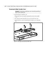
controller board
photograph 4-19
rear components 1-3
removing 4-20
replacing 4-23
D
dimensions 5-1
display
photograph 4-13
release latch 1-2
replacing 4-16
switch 1-2
dissipating floor mats 3-2
E
electrostatic
precautions 3-2
preventing 3-2
exploded view of spare parts 2-2
F
features
front panel components 1-2
rear components 1-3
frequency, horizontal and
vertical 5-2
front panel components 1-2
button
left pick 1-2
right pick 1-2
cap lock LED 1-2
display
release latch 1-2
switch 1-2
front plastic bezel 1-2
nine hot keys 1-2
on-screen display
activation button 1-2
scroll down button 1-2
scroll up button 1-2
programmable wizard key 1-2
scroll
left and right button 1-2
lock LED 1-2
up and down button 1-2
track ball 1-2
front plastic bezel 1-2
photograph 4-4
removing 4-8
replacing 4-8
H
heel straps, grounding
methods 3-2
help
additional sources viii
Compaq authorized resellers,
telephone numbers viii
Compaq website viii
technical support telephone
numbers viii
horizontal frequency 5-2
humidity 5-2
I
icons, symbols on equipment vi
illustrated spare parts list 2-1
illustrations
disconnecting cables 4-15
exploded view of TFT5600
RKM 2-2
identifying
front panel components 1-2
rear components 1-3
removing
AC brick 4-18
clutch covers 4-6
grounding clip 4-14
keyboard assembly 4-12, 4-33
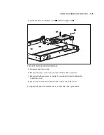
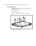
metal controller cover 4-21,
4-31
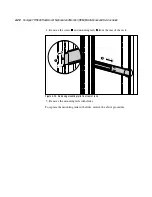
mounting rail brackets from rear
of rack 4-28
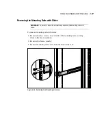
mounting rails with slides 4-27
palm rest 4-7, 4-11
Содержание 5600 - TFT RKM
Страница 28: ...Removal and Replacement Procedures 4 9 SPS KEYBOARD 230978 XXX Figure 4 6 SPS KEYBOARD 230978 XXX...
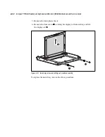
Страница 32: ...Removal and Replacement Procedures 4 13 SPS DISPLAY LCD 15 229842 001 Figure 4 10 SPS DISPLAY LCD 15 229842 001...
Страница 38: ...Removal and Replacement Procedures 4 19 SPS BD CNTRLR 229847 001 Figure 4 16 SPS BD CNTRLR 229847 001...


