


6. Error rectification
21
6
Error rectifica tio n
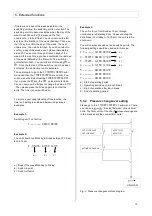
6.1 Warnings
Warning messages are shown in the 3rd display row.
The red light signal on the DELCOS
Pro
also flashes
slowly.
Warning messages do not result in the compressor
shutting down. However ignored warnings may cause
faults.
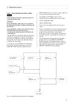
6.2 Faults
In order to protect the unit, all detected faults result in
the compressor shutting down immediately or do not
permit the compressor to be started.
The faults are shown in the third display row. The red
light signal on the DELCOS
Pro
also flashes quickly.
Faults have to be rectified before the start and then
acknowledged using the key. The unit can now be
started again.
6.3 Checklist
Loose connections, connection plugs, defective power
supplies or non-observance of the installation notes
generally result in a large number of error patterns. It is
therefore not unusual for the errors shown to be traced
back to another cause.
Please therefore always observe the following checklist:
1. The unit's supply voltage must be within the
permissible limits.
2. The control transformer must be set to any local -
deviating mains voltages (see circuit diagram).
3. The switch panel temperature must not exceed
55 °C.
4. All remote controls fitted at a later date (remote
On/Off) must be managed without a connection
relay at max. 20 metres from the control cabinet.
5. When commissioning and carrying out maintenance
work, check that all connections screws and plugs
are tight.
6. The power supply must have an adequate cross-
section. When designing the cable, please therefore
note the type of routing, cable length and the
conductor temperatures expected.
7. When retrofitting switching devices, the control
transformers must never be 'tapped' as they could
be overloaded.
8. Only ever use genuine CompAir spare parts.
9. Do not connect up extra switching or measurement -
devices without the consent of CompAir.
10. Do not route any measurement recorders out of the
unit.
11. If you have any technical queries, have the following
information to hand to assist with a quick and
specific fault rectification:
- Unit type / product number
- Order number
- Circuit diagram drawing no. and ID
- Information about the unit's operating conditions
- Information about the accessories your fitted
later on (remote controls etc.)
- Other conversions/add-ons on your unit
undertaken later on
- An accurate description of the fault that has
occurred.
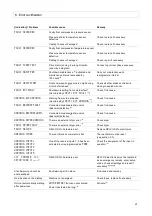
6.4 Table of faults / warnings
The next few pages contain the fault table for the
DELCOS
Pro
, the possible causes of faults and
suggestions on how to remedy them.


