background image

CompAir UK Ltd

 PUBLICATION 98407/1050 

Page 27 


8  OPERATION AND ROUTINE MAINTENANCE 

8.1  OPERATION AND GENERAL MAINTENANCE 

Commissioning procedure should be used:- 
(a) For first commissioning run. 
(b) Following overhaul. 
(c) After standing idle for a long period. 
Crankcase oil needs to be changed after major overhaul.  
Starting procedure should be observed after valve cleaning/change. 
Keep the exterior of the compressor clean, especially pipe connections and joints, as this will 
assist in detecting any leaks. Ensure finned intercooler is clean at all times. 
Monitor and record pressures and temperatures in order to give advanced warning of any 
malfunction. Ambient conditions, especially temperatures, will vary readings but they are usually 
within plus or minus 4%. 
Marking the pressure gauge glass at the normal running pressure will allow easy comparisons of 
pressure to be made in the future. 

8.2 STARTING 

UP 

Check crankcase oil level. Top up if necessary with recommended oil until the level up to the 
maximum level mark on sight glass.  
Set stop valves and adjust trip circuits correctly. 
Check that all loose equipment and tools are clear of compressor and ancillary equipment. 
Operate starter, and bring on to load. Oil level will drop in glass when machine is running. 
Unloader/bleed valve will close automatically. 
On engine sets start in accordance with engine suppliers operating manual and close manual 
drain/unloading valve only when engine is up to speed. Bring on to load as for electric sets. 
Whilst the compressor is running, listen for any noises indicative of mechanical failure. Stop and 
investigate if:- 
1) Any uncharacteristic noises commence. 
2) Any safety valve opens. 


WARNING:- 
THE CAUSE OF A SAFETY VALVE OPENING MUST BE INVESTIGATED AND RECTIFIED. 
DO NOT ATTEMPT TO PREVENT A VALVE OPENING BY TAMPERING WITH ITS SETTING. 
THIS IS EXTREMELY DANGEROUS. 


8.3  RUNNING ON LOAD 

Check temperatures and monitor gauges for normal pressures. 
When fitted, operate manual drains at 30 minute intervals.  
 

NOTE:

 These machines will normally be under automatic stop/start control unless engine driven, 

when manual control is more usual. 

8.4 STOPPING 

When not fitted with automatic stop/start controls the compressor can be stopped by the push to 
stop button on the starter. 
Always isolate electric supply at the end of an operational duty period. 
On engine sets - stop the engine in accordance with engine operating manual and manually open 
drain/unloader valve to allow unloaded restart when required. 

Содержание 5211.2.IA

Страница 1: ...ORDER NUMBER MACHINE NUMBER PUBLICATION NUMBER 98407 1050 ISSUE DATE JAN 2009 issue 2 CompAir UK Ltd CompAir UK Ltd Reavell House 53 56 White House Road IPSWICH ENGLAND IP1 5PB Telephone 44 0 1473 242...

Страница 2: ......

Страница 3: ...0 2 AMENDMENTS 11 3 LOGSHEET 13 4 GENERAL DESCRIPTION AND OPERATION 15 4 1 GENERAL 15 4 2 BEARINGS 15 4 3 VALVES 15 4 4 LUBRICATION 16 4 5 DRIVE 16 4 6 INSTRUMENTATION 16 4 7 AUTOMATIC STOP START CONT...

Страница 4: ...NERAL MAINTENANCE 27 8 2 STARTING UP 27 8 3 RUNNING ON LOAD 27 8 4 STOPPING 27 8 5 STANDING IDLE 28 9 MAINTENANCE SCHEDULE 29 9 1 GENERAL 29 9 2 DAILY 29 9 3 WEEKLY 29 9 4 RECOMMENDED MAINTENANCE SCHE...

Страница 5: ...r the failure to maintain this equipment in accordance with the maintenance instructions may invalidate the WARRANTY cause equipment failure create unsafe or hazardous conditions or result in damage t...

Страница 6: ...e 44 0 1473 242000 Notes Address CompAir UK Ltd Reavell House 53 56 White House Road Ipswich IP1 5PB ENGLAND Telephone 44 0 1473 242000 Fax 44 0 1473 745451 Contact Names Parts Telephone 44 0 1473 242...

Страница 7: ...e tel 44 0 1473 242097 and Parts department tel 44 0 1473 242000 Fax 44 0 1473 743468 and Sales 44 0 1473 242000 Fax 44 0 1473 743482 at CompAir UK Ltd Ipswich UK The information in this Manual was co...

Страница 8: ...rranty are set out in the Standard Conditions of Sale MAINTENANCE To ensure continued trouble free operation of the compressor it is important that periodic maintenance and servicing are carried out i...

Страница 9: ...tential hazard The WARNINGS in this manual are therefore not all inclusive If the user employs an operating procedure an item of equipment or a method of working which is not specifically recommended...

Страница 10: ...o passers by through loose clothing being sucked into compressor intake Ensure that the discharge pipe from the compressor to the user pipework receiver or storage is free to expand and that no flamma...

Страница 11: ...rsons under qualified supervisor must carry out maintenance repair and modifications The compressor will have a preserving oil applied to interior surfaces Oil lubricated models Oil free models will h...

Страница 12: ...ipe bores or any component carrying a flow of air or gas during normal operation If chlorinated hydrocarbon substances are used for cleaning safety precautions must be taken against toxic vapours whic...

Страница 13: ...UK Ltd PUBLICATION 98407 1050 Page 11 2 AMENDMENTS ISSUE No REASON DATE PAGE No 1 NEW JUNE 2001 ALL 2 NEW SERVICE PLAN JAN 2009 31 3 4 5 6 7 8 9 10 11 12 13 14 15 16 17 18 19 20 21 22 23 24 25 26 27 2...

Страница 14: ...CompAir UK Ltd PUBLICATION 98407 1050 Page 12...

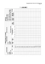
Страница 15: ...BLADES SERVICE PLAN NUMBER DELY PRESS BAR PSI 5 4 INSTALLED AT DATE INSTALLED 3 2 STAGE PRESSURES BAR PSI 1 DELY TEMP C PRIME MOVER TYPE POWER DRIVE STAGE TEMP C HRS RUN 50 100 500 1000 1500 2000 250...

Страница 16: ...CompAir UK Ltd PUBLICATION 98407 1050 Page 14 REMARKS DATE REMARKS DATE...

Страница 17: ...and 1st stage separator to the second stage On exit from the second and final stage air flows through a small integrally cast pulsation damper before going through and a cooling system positioned in t...

Страница 18: ...ing on the pressure switch is reached the switch contact closes initiating the start up of the motor On reaching the pre set high pressure setting the switch contact opens and stops the motor Control...

Страница 19: ...arge pressure 20 bar Maximum discharge pressure continuous 42 bar Maximum discharge pressure intermittent 45 bar 30 minutes on maximum load 30 minutes off 5 4 SAFETY VALVE SET PRESSURES First Stage 6...

Страница 20: ...ower than normally recommended temperature duties consult CompAir UK Oil capacity of crankcase litres 1 4 Recommended silicone grease for assembly Dow Corning MS33 Running in low pressure conditions o...

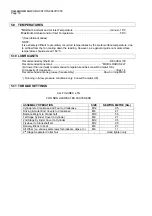
Страница 21: ...n Rings 2 0 01 0 05 0 25 Oil Control Ring 2 0 03 0 07 0 27 Piston Ring Width Piston Rings 1 4 01 3 99 3 87 Oil Control Ring 1 5 99 5 98 5 84 Piston Rings 2 3 99 3 97 3 87 Oil Control Ring 2 4 5 4 48 4...

Страница 22: ...CompAir UK Ltd PUBLICATION 98407 1050 Page 20...

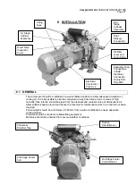
Страница 23: ...work to be carried out when required Fan cowl inlet should be a minimum of 300 mm from a wall or bulkhead to ensure adequate cooling air flow Provision should be made for suitable lifting equipment M...

Страница 24: ...790 1981 See SECTION 10 for details on DIRECT DRIVE 6 6 CONNECTIONS PIPEWORK AND FITTINGS Careful thought should be given to the system and piping lay out with all piping and connections suitable for...

Страница 25: ...the compressor are determined on an hours run basis some accurate method of operational time recording should be employed to indicate when routine maintenance becomes due For this purpose it is recom...

Страница 26: ...T ON LOW PRESSURE SIGNAL FROM MPS ON REACHING HIGH PRESSURE COMPRESSOR STOPS UNLOADS AND DRAINS IF COMPRESSOR RUNS FOR 30 MINUTES WITHOUT STOPPING DRAINS OPEN AUTOMATICALLY FOR 5 SECONDS 10 SECOND DEL...

Страница 27: ...air and re insert in casing Ensure silencer bore and pipework are clean Fill with the correct grade of lubricant until oil level is between the minimum and maximum level marks on the sight glass IMPO...

Страница 28: ...warning of any malfunctions 7 4 MAINTENANCE After First 15 Hours Running Time Ensure that alignment and belt tensioning is correct After First 50 Hours Running Time Change the crankcase oil Remove th...

Страница 29: ...ressor and ancillary equipment Operate starter and bring on to load Oil level will drop in glass when machine is running Unloader bleed valve will close automatically On engine sets start in accordanc...

Страница 30: ...ill crankcase with Shell Ensis 20 to the correct level indicated by the crankcase sight glass Run the compressor Switch off the compressor Remove first and second stage cylinder covers and valves Wipe...

Страница 31: ...st cater for a wide variety of operating duties ambient conditions and methods of control Periods given in this manual allow for the worst combination and are also based on preventative maintenance ra...

Страница 32: ...CompAir UK Ltd PUBLICATION 98407 1050 Page 30...

Страница 33: ...int valve to cyl 1 X X 9 8 Replace 2nd stage valve Valve 1 X Check condition of 2nd stage cylinder X 10 8 Remove 2nd stage cylinder O ring cyl to c case 1 X 11 8 Replace 2nd stage piston rings gudgeon...

Страница 34: ...n Hours 50 1000 2000 3000 4000 Task Preparatory Task Task Description Parts Provided Qty X X X X Check tightness of all fasteners PARTICULARLY COOLER CLAMP FASTENERS X 18 4 Inspect 1st stage cylinder...

Страница 35: ...Renew any plates which are indented cracked warped or have wear grooves which exceed 1 10th of the plate thickness If the seats show severe wear or indentations the complete valve assembly must be re...

Страница 36: ...six cylinder cover retaining nuts and remove cylinder cover complete with integral cast pulsation damper Remove valve and discard the joints between cylinder cover and valve valve and cylinder 10 4 2...

Страница 37: ...FROM THE RECEIVER NOTE A Safety valve opening indicates excessive pressure and under NO CIRCUMSTANCES must a safety valve be screwed down to accommodate excessive pressure THIS IS DANGEROUS If safety...

Страница 38: ...CompAir UK Ltd PUBLICATION 98407 1050 Page 36...

Страница 39: ...educe operating duty Insufficient cooling air Check location and area ventilation Reduced cooling efficiency Examine cooler s for partial blockage Cooling fan clogged Clean fan Cylinder fins clogged o...

Страница 40: ...07 1050 Page 38 How to order spares IN ORDER TO AVOID UNNECESSARY DELAY PLEASE QUOTE 1 Complete invoicing and shipping address 2 Machine Model Reference No 3 Machine No 4 Item Reference 5 Part No 6 De...

Страница 41: ...LIST CRANKCASE 001 005 RUNNING GEAR 006 010 1st 2nd STAGE CYLINDERS 011 019 COOLING ASSEMBLY 020 024 COOLING ASSEMBLY Cont 025 035 MAINTENANCE KITS Append 1 Due to our policy of continuous improvement...

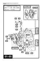
Страница 42: ...01 05 02 1 3 2 4 5 9 5 10 TORQUE WRENCH SETTINGS 5 10 5 11 5 13 M8 27 Nm 20 lbf ft 03 6 M12 95 Nm 70 lbf ft END FLOAT 0 15 0 35mm 5 4 5 17 5 16 5 1 5 15 5 13 5 9 5 11 5 3 5 12 5 2 5 6 5 14 6 2 1 5 3...

Страница 43: ...12 Plug 3 8 BSPT Seal for Oil Level Gauge Oil Level Gauge E61127 50 C202813 2 D66720 12 53 E61127 PS1113 3 W0222 0062 95111 7 95405 944 95640 14 98540 1001 1 1 8 1 8 1 8 1 1 1 The following parts are...

Страница 44: ...8 5 M10 55 Nm 40 lbf ft 10 10 M12 95 Nm 70 lbf ft T D C CLEARANCES st 1 stage 0 25 1 15mm nd 2 stage 8 25 9 05MM 06 10 1 1b 1a 06 2 3 1 07 2 3 3a 3b 10 5 b d 10 1 a c 10 9 10 3 10 7 10 6 10 11 10 10 1...

Страница 45: ...45 1 1 1 1 1 2 1 09 a b c d CONN ROD 1st STAGE Parts Bush S E Conn Rod Splash Pin Bearing B E C203778 C203777 D101436 E1880 98076 1127 1 1 1 1 1 09 1 a b c d CONN ROD 2nd STAGE Parts Conn Rod Splash P...

Страница 46: ...407 1050 Page 44 TORQUE WRENCH SETTINGS 14 3 15 9 M8 27 Nm 20 lbf ft 13 4 M12 95 Nm 70 lbf ft 15 13 15 10 15 13 11 19 3 15 12 15 7 14 1 15 6 15 5 15 4 15 9 13 2 1 4 15 1 15 14 15 15 15 11 15 2 15 8 2...

Страница 47: ...1 2 3 4 5 CYLINDER 2nd STAGE Parts Stud M12 x 93 Stud M12 x 60 Cylinder Nut M12 O Ring E61566 100 D66720 12 111 D66720 12 78 E61538 95111 7 95602 96 1 4 2 1 6 1 14 1 2 3 4 CYLINDER 1st STAGE Parts St...

Страница 48: ...0 42 20 52 20 23 d 20 32 c a 20 17 b c a 20 10 b 20 42 20 9 20 28 20 3 20 33 20 12 20 39 20 13 20 2 20 21 20 41 20 33 20 6 20 37 20 49 20 13 20 1 20 36 20 25 20 38 20 9 20 9 inside 20 48 20 35 20 40 2...

Страница 49: ...PE ASSY Parts Tube Copper 3 4 x 16 swg x 15 Elbow 1 2 BSPT x 3 4 O D C202866 W3225 1132 98156 2616 0 0 0 20 11 a b c 20 12 20 12 1 20 13 DELY PIPE ASSY 1ST STAGE Parts Tube Copper 25 x 1 6 x 15 Connec...

Страница 50: ...24 for details of pressure gauge pipe 20 8c 20 51 30 4 h n c f 35 11 35 10 35 8 35 6 35 7 35 9 35 8 35 10 35 3 35 1 30 1 30 3 30 2 25 4 CONNECTION PLASTIC BODY BSP METAL 1 8 BSP b 35 4 c a 35 6 35 2...

Страница 51: ...NG M8 AXIAL FAN CLAMP PIPE 3 4 COOLER INTERSTAGE TIE CABLE GAUGE PRESSURE 0 70 bar VALVE SAFETY 2nd STAGE 33 bar VALVE SAFETY 2nd STAGE 49 5 bar VALVE NON RETURN SEAL COPPER 1 4 BSP SEAL COPPER 3 8 BS...

Страница 52: ...24 for details of pressure gauge pipe 20 8c 20 51 30 4 h n c f 35 11 35 10 35 8 35 6 35 7 35 9 35 8 35 10 35 3 35 1 30 1 30 3 30 2 25 4 CONNECTION PLASTIC BODY BSP METAL 1 8 BSP b 35 4 c a 35 6 35 2...

Страница 53: ...5602 61 98150 1007 98156 2575 98650 1824 95000 257 95028 136 95148 14 95179 6 1 0 0 0 0 0 0 0 0 0 0 0 0 0 0 1 1 2 1 31 a b c d COOLER EXTENTION ASSY parts Tube 3 4 x 16g x 126 Elbow 3 4 o d x 1 2 BSPT...

Страница 54: ...int 2nd Stage Valve to Cover Joint D E O E Bearing Hsg to Crankcase O Ring 1st Stage Valve to Cover O Ring 1st 2nd Stage Cyls to Crankcase O Ring 1st Stage Valve to Cylinder Washer Copper 1 1 4 BSP Wa...

Страница 55: ...locity stream can force dirt into the spaces between windings etc Grease removing solvents should only be used very sparingly so as not to damage impregnating varnish or insulation Bearings are charge...

Страница 56: ...ntial 0 07 bar 98524 1136 Setting Range 3 70 bar g rising 98524 1137 Setting Range 3 66 5 bar g rising 98524 1210 Setting Range 5 40 mbar 98524 1212 Setting Range 70mbar 70bar The switch transforms a...

Страница 57: ...erminals marked Pressure Switch Remove cover to set pressure setting using a pressure gauge Note Switches are pre set and do not usually need adjusting Please confirm with Engineering at CompAir UK Lt...

Страница 58: ...hours and every 2000 hours more frequently on arduous duties such as more than 6 starts per hour on auto stop start operation check the following Ensuring compressor is isolated from mains supply rem...

Страница 59: ...P 12mm 16 98516 1043 110 50 AC BSP 12mm 16 98516 1044 24 DC BSP 12mm 16 98516 1048 6 DC BSP 1 6mm 60 98516 1049 12 DC BSP 1 6mm 60 98516 1050 24 DC BSP 1 6mm 60 98516 1051 48 DC BSP 1 6mm 60 98516 105...

Страница 60: ...ction Amps pin to DIN 46242 Connector To DIN 43650 Protection IP65 Cable thread size PG9 Coil Class H 180 C insulation Coil duty Continuous Voltage tolerance from normal 10 to 10 Working fluid Air wat...

Страница 61: ......
Страница 62: ...d has no control Such hazardous conditions may lead to accidents that can be life threatening cause substantial bodily injury or result in damage to the equipment CompAir UK Ltd can bear no responsibi...

Отзывы: