background image

IN2SMS[POE](C,U)_REV–   10/27/11   PAGE 5

INSTALLATION AND OPERATION MANUAL 

CLFE4+2SMS[POE](C,U) SERIES

TECH SUPPORT: 1.888.678.9427

Table 5 – Troubleshooting Guide

Problem

Steps to Take

Indicating LEDs not lighting

Check that power is properly applied to the unit using the correct connector pair.

No Communication

Check Ethernet Link LEDs, Extended Link LEDs, All Connections, Local/Remote switch is set properly. 

Verify that Local units are installed at the head end and that Remote units are installed in the field.

Verify that the Data Rate switches are set to the same data rate on both the Local and Remote units.

Bad Video or Data

Make sure Data Rate and 1/4 Pair Switches are set properly, and the extended distance is within specifications (see Table 

4 – Approximate Maximum Extended Distances).

Units not reaching estimated max 

distances over COAX or UTP

Check extended distance cable and connections. Try connection on a short cable to eliminate possibility of faulty cabling.

Check that the extended distance wire is connected to Extended Distance Port.

Verify that there is no additional equipment (e.g. surge protector) on the Extended Link. The cable should be continuous from 

end to end, with no active components.

Table 4 – Approximate Maximum Extended Distances¹

Media

COAX - RG59/U

UTP - 1 pair

UTP - 4 pair

Extended Port Data Rate

10M

100M

10M

100M

10M

100M

Extended Distance

1

5,000 ft 

1,524 m

2,000 ft 

610 m

3,000 ft 

914 m

1,000 ft 

305 m

3,000 ft 

914 m

2,000 ft 

610 m

1

  Distance figures are obtained using in-house testing mirroring installations. Factors such as coaxial/copper cable quality, the number of connectors/

splices in the cable run, the use of PoE, and environmental conditions encountered within the installation may affect the actual transmission 
distance, and should be taken into consideration.

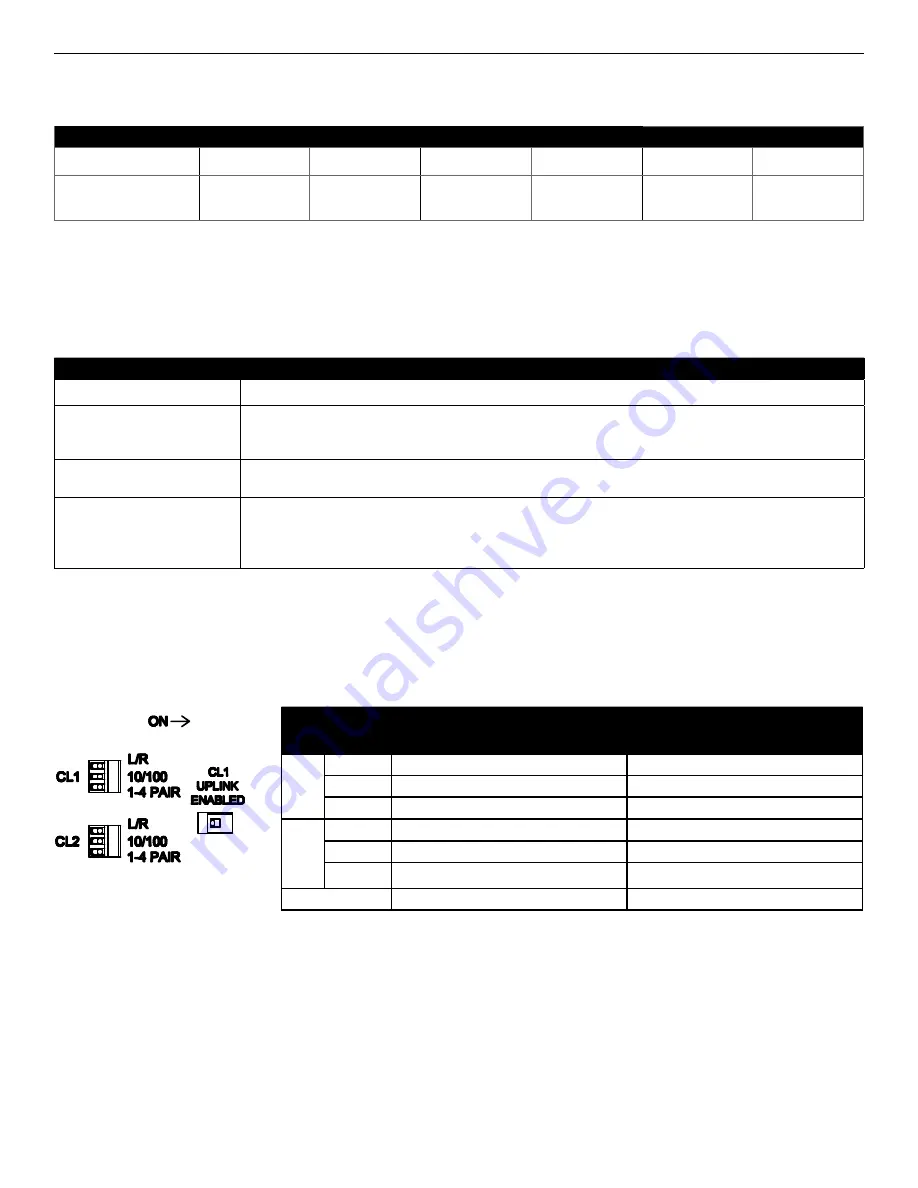
Figure 3 – DIP Switch Settings

Table 6 – DIP Switch Settings

DIP Switch

Setting Effect

On

Off

CL1

L/R

Unit will operate as remote / field

Unit will operate as local / head-end

10/100

100 Mbps Data Speeds

10 Mbps Data Speeds

1 - 4 PAIR

1 Pair Twisted Wires 

4 Pair Twisted Wires

CL2

L/R

Unit will operate as remote / field

Unit will operate as local / head-end

10/100

100 Mbps Data Speeds

10 Mbps Data Speeds

1 - 4 PAIR

1 Pair Twisted Wires


4 Pair Twisted Wires

CL1 UP LINK

Enabled

Disabled

Содержание CLFE4+2SMS Series

Страница 1: ...erLine extension port into a further CopperLine extension port that forwards this data to the next CopperLine network device There is no programming required to use this product The ComNet CLFE4 2SMS C U comes pre programmed preventing network video flooding with DIP switch selection of the first CopperLine port as an uplink or as an unmanaged switch Ports 1 4 of the CLFE4 2SMSPOE C U can supply u...

Страница 2: ... 45 Port and Link Activity L A Indicating LED See Installation Instructions Step 4 See Table 3 Indicating LEDs 4 Channel 2 Extended Distance over UTP RJ 45 Port and Link Activity L A Indicating LED See Installation Instructions Step 4 See Table 3 Indicating LEDs 5 Channel 1 Extended Distance over UTP Port DIP Switches for Local Remote Operation Data Speed and Wire Pairs See Installation Instructio...

Страница 3: ...Activity L A Indicating LED See Installation Instructions Step 4 See Table 3 Indicating LEDs 4 Channel 2 Extended Distance over UTP RJ 45 Port and Link Activity L A Indicating LED See Installation Instructions Step 4 See Table 3 Indicating LEDs 5 Channel 1 Extended Distance over UTP Port DIP Switches for Local Remote Operation Data Speed and Wire Pairs See Installation Instructions Steps 1 3 6 Cha...

Страница 4: ... devices 4 SET CL1 UP LINK ENABLED DIP SWITCH Set the Up Link switch to the ON position to enable Uplink port features 5 CONNECT EXTENDED WIRING Connect Extended Distance Port to field wiring 6 CONNECT NETWORK WIRING Using Cat5 5e connect Local unit to network and Remote unit to camera 7 CONNECT POWER Connect power to unit per the following table NOTE Remove Electrical Connector for Rack Mount Uni...

Страница 5: ...d Distance Port Verify that there is no additional equipment e g surge protector on the Extended Link The cable should be continuous from end to end with no active components Table 4 Approximate Maximum Extended Distances Media COAX RG59 U UTP 1 pair UTP 4 pair Extended Port Data Rate 10M 100M 10M 100M 10M 100M Extended Distance1 5 000 ft 1 524 m 2 000 ft 610 m 3 000 ft 914 m 1 000 ft 305 m 3 000 ...

Страница 6: ...Uplink disabled on the units CL1 PC Connections on Ports P1 P4 CLFE4 2SMS C U CLFE4 2SMS C U CLFE4 2SMS C U CL1 CL1 CL2 Figure 4 Typical Application Figure 5 Application Diagram With Multicast Traffic IGMP Enabled Uplink enabled on the units CL1 PoE Camera Connections on Ports P1 P4 CNGE3FE7MS2 CNGE3FE7MS2 CLFE4 2SMS C U CLFE4 2SMSPOE C U CLFE4 2SMS C U CL1 CL1 CL2 Up layer Network CL X SFP CL X S...

Страница 7: ...temperature of the rack environment may be greater than room ambient Therefore consideration should be given to installing the equipment in an environment compatible with the maximum ambient temperature Tma specified by the manufacturer B Reduced Air Flow Installation of the equipment in a rack should be such that the amount of air flow required for safe operation of the equipment is not compromis...

Отзывы: